This thread has been locked.

If you have a related question, please click the "Ask a related question" button in the top right corner. The newly created question will be automatically linked to this question.

ADS124S08: Register setup for current source

Part Number: ADS124S08

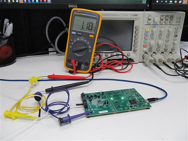
I need help setting up the ADS124S08EVM (evaluation board)  to output a current on any output. I am not getting any current.  I have checked the jumpers and tried a different Evaluation module.    I have included my setup using the with the setup software with my attempt to output  current on A4.  I am using the Refresh/Sync button to "send" the new configuration to the development board.  I am obviously missing something.

Any help would be appreciated.

New Microsoft Word Document (8).docx

  • Hi Kevin,

    Welcome to the E2E forum! There must be a completed current path to AGND.  This is sometimes overlooked when connecting to an external sensor.  So what do you have connected to AIN4 and does the path connect back to AGND on the EVM?

    Best regards,

    Bob B

  • I am using an external wire attached to the AIN4 terminal and a multimeter to that wire, measuring from DGND to AIN4.  I have checked for a bad fuse in the multimeter by measuring from a 4.7K pullup to ground.  If it is wired to the datasheet, the analog ground should be close enough to DGND for this.  I have also checked this with a multimeter.  I am currently trying check my ability to communicate to the chip with external hardware, so the setup is extremely simple.

    Could you confirm that the only setup registers for current output are the IADCMUX and the  IADCMAG registers?

  • Hi Kevin,

    The IDAC current sources use the internal reference to establish the proper current selected.  So you must also turn on the internal reference for the IDACs to source current by selecting the appropriate bits in the reference control register (REF - 0x05).  You do not need to select the internal reference as the ADC reference, but it must be turned on to enable the IDAC current.

    Best regards,

    Bob B  

  • Thank you, I can now set the current output.  The current output does track to my meter.  However, at current levels 1500uA and 2000uA,  i read about 1.17mA to 1.18mA.

    Is there anything else I should look at?

  • Hi Kevin,

    This sounds like you might be exceeding the compliance voltage.  The total voltage drop from the IDAC pin to analog ground cannot exceed the compliance voltage of AVDD - 0.6V for currents greater than 750uA.  Previously you mentioned using a 4.7k resistor to ground.  Using this value of resistance will exceed the compliance voltage.  In other words you need to make sure that there is enough headroom in the IDAC path that does not exceed the compliance voltage as you cannot create a voltage from the IDAC current that is more than 600mV from the supply and maintain constant current.

    Best regards,

    Bob B

  • I have marked this as solved, but I do think there is sufficient headroom when I marked the currents.  I was measuring from the AIXX pin directly to digital ground, which is measured with a meter to shorted to AGND.  I was using the ADS124S08EVM board configured to have 5V on the analog side.

  • Hi Kevin,

    Take a look at the ADS124S08EVM schematic that is toward the end of the user's guide.  Note that when you use the AIN4 to route the IDAC current there is a filter resistor in the path that is 4.12k.  This resistor must also be included in the IDAC compliance path. AIN3 does not have a resistor in the path (only a reverse protection diode) which should allow you to measure the current correctly.

    Best regards,

    Bob B 

  • I have included a picture of the setup I am using.  I am getting the 1.17-1.18mA current for all available analog pins.  It is literally a current meter from AIN1 to GND.  With this setup I should have a compliance voltage of about 4V nominal (5V - (less than one volt across the current meter)).  

    I am using the "Delta-Sigma ADC EvaluaTIon Software" with the following register changes:

    REF = 0x12

    IADACMAG = 0x09

    IDACMUX = 0x1F

    This should give me about 2mA.

  • Hi Kevin,

    Thanks for the picture as this always helps.   I can't tell for sure, but you should be connected to the A2, and the IDACMUX setting should be 0x3F and not 0x1F.  You want the current to come out AIN3.

    If you are connected to A1 and the current flows out AIN1, you still have the same issue as before as there is a filter resistor in the path.  Please refer to the schematic.

    Best regards,

    Bob B

  • When I reviewed the schematic in the file sbau272a.pdf, I could not see any series resistance from the AIN1 I.C. pin to the connector.  The 1K resistor shows potential current paths to REFP1 and AIN5 that should be negligible, particularly for higher current settings.  Per my reading of the datasheet, REFP1 and AIN5 should only have leakage currents.

    Perhaps this can best be explained by example.  The values below are what I measured when I changed the value of IMAG.  I got very similar result on all the available analog inputs.  

    the following table shows similar results 

    IMAG:

    Setting    Measured

    10uA           10uA

    50uA            49.6u

    100u A         99.6uA

    250uA          248.6uA

    500uA          496uA

    750uA          745uA

    1000uA        993uA

    1500uA        1154uA

    2000uA         1160uA

  • I found my error.  For some reason, I did not see the 4.12K resistors.

    Thank you for your patience.

    Everything now makes perfect sense.