This thread has been locked.

If you have a related question, please click the "Ask a related question" button in the top right corner. The newly created question will be automatically linked to this question.

ADS1261EVM: ADS1260 : Need to measure uA current ADC solution

Part Number: ADS1261EVM
Other Parts Discussed in Thread: ADS1260, , ADS1235, ADS125H01, ADS1261, REF6025

Hello,

I would like to design a solution that can measure uA current measurement solution.

Here's the specification:

1. Measure 0~50mA current.

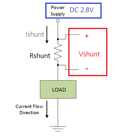
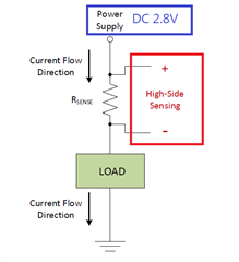
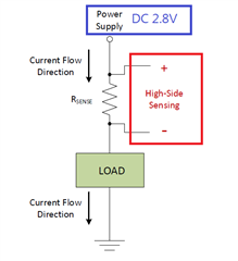
2. We only use one shunt resistor to measure the current.

3. The  current shunt resistor will be 100mohm ~ 1 ohm_R1210. ( It's ok to get larger value of the shunt resistor.)

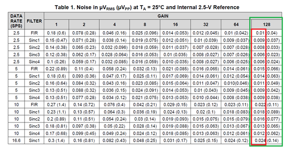
4. The resolution we expect is 1uA.

5. High-Side Sensing and the Power Supply will be 2.8V

→ I've got the suggestion of ADS1260 and  read the datasheet of ADS126x and ADS1261EVM.

Here's some questions:

  1.  Is it ok to pick the shunt resistor of 100mohm ~ 1 ohm_R1210 or other suggestion?

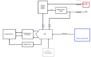
  2.  From 2., after pick the right risistor , what the schematic it will be? Is its enough of using the SBAU293A -ADS1261 and ADS1235 Evaluation Module_P24~P31 for reference design or other suggestion?

  • Hi Jax,

    Thanks for your questions.

    The other e2e thread you linked to ("ADS125H01: Need to measure uA current ADC solution") details the process used to determine what gain and data rate are required to get the precision you need using the ADS1260. Can you please give this a try and see what you come up with?

    Same for the schematic - please make an attempt at what you think the schematic should look like and then we can offer advice.

    -Bryan

  • Hi Bryan,

    Thanks for your reply.

    By the description of the e2e thread("ADS125H01: Need to measure uA current ADC solution"), I come up with the following statements:

    If I choose R-shunt = 100mΩ
     (1) Vsense_Max = Isense_Max x Rshunt = 50mA x 100mΩ = 5mV
     (2) Dynamic Range = Isense_Max / Iresolution = 50mA / 1uA = 50000
     -> (3)Vresolution = Vsense_Max / Dynamic Range  = 0.1uV

     
    Then, use the Table 1.  in Datasheet of ADS1260 to find the condition meeting "uV_RMS" performance.


    If we don’t consider about “data rate”. (Its enough for us with above 2.5 sample per second.)

    And we choose “gain” = 128.

    I can use all of the condition of the table, right? (The value < 0.1uV is safe.)


    Here comes some questions:
    1. Why the condition to consider is
    "uV_RMS" instead of "uV_pp "?


    2. With Higher “Gain” (Ex: 128), are there some limits or side effects?

    3. With Higher “Filter type” (Ex:FIR4), are there some limits or side effects?


    By the way, I'm drawing the schematic. It will be completed for you to check and seeking some advice.


    Best Regards.

  • Hi Jax,

    Thanks for coming to these conclusions. For your information, Table 1 continues onto the next page of the datasheet, so if your noise target was ~100nVRMS, then you could sample up to 400 SPS and still get the required noise performance.

    The difference between RMS and PP noise is statistical, where RMS is +/-1 standard deviation of the dataset while PP is typically +/-3 or +/-3.3 standard deviations. Therefore, this information tells you the probability that the noise will be within the level specified, where RMS is sort of like a "typical" case and PP is more like a "maximum" (though it is theoretically possible for the noise to be >PP value). It is up to you to determine if you want to use RMS or PP. You can also check out our Precision Labs training series on ADC noise (section 6): https://training.ti.com/ti-precision-labs-adcs

    With higher gain, you would need to consider the common-mode range of the PGA, as this tends to get narrower as the gain increases. You can use the Excel calculator tool to help you determine if your input signals are within the input range of the PGA: https://www.ti.com/lit/zip/sbac200

    The higher the filter type, the longer the latency is, especially when multiplexing through channels. You can see this in "Table 8: Conversion Latency" in the ADS1260 datasheet. For example, if you choose a data rate of 100 SPS and SINC1 filter, the latency for one channel conversion is 10.43 ms. However, if you choose a data rate of 100 SPS and a SINC4 filter, the latency increases to 40.43 ms. So the higher-order filter takes longer to settle, but it also reduces the noise.

    -Bryan

  • Hi Bryan,

    Thanks for your reply.

    We want to measure the small electronic products’ power consumption at specific moment and

    We don’t put the real time response for the higher priority than the noise quality.

    So it’s OK to wait some milliseconds for the value conversion.


    After read your information and the Excel calculator tool, I try to get something:

    ----------------------------------------------------------------------------------------------------------

    Specification:

    - Measure 0~50mA current.

    - We only use one shunt resistor to measure the current.

    - The current shunt resistor will be 100mΩ.

    - The resolution we expect is 1uA.

    - High-Side Sensing and the Power Supply will be 2.8V.


    (1) Vshunt_Max = Isense_Max x Rshunt = 50mA x 100mΩ = 5mV
    (2) Dynamic Range = Isense_Max / Iresolution = 50mA / 1uA = 50000
    (3) Vresolution = Vshunt_Max / Dynamic Range  = 0.1uV

    ---------------------------------------------------------------------------------------------------------

    1. PGA Gain: By Table 1 in ADS_datasheet, I would set it to 128.
    2. Supply Voltage(s): I have a DC5V power source. Set AVDD to 5V and AVSS to 0V.
    3. Actually, I have no idea of setting “Reference voltage(s) in Excel.

    So I read the datasheet and guess in the follows:

    By 9.3.3 Reference Voltage in ADS1260_datasheet,

    - If I use 9.3.3.1 Internal Reference: Set VREFP to 2.5V and VREFPN to 0V.
    - If I use 9.3.3.3 AVDD - AVSS Reference (Default): Set VREFP to 2.5V and VREFPN to 0V. (The same to AVDD/AVSS)
    →Need some advises and explanations for reference voltages settings.

    1. VIN_DIFF: I guess it’s Vshunt_Max. Set it to 0.005V
    2. VIN_CM: I guess it’s High Side Voltage. Set it to 2.8V

      Final, I get two results as follows.


      It looks safe of Input Voltage settings with Gain =128.


      Need some help and advises of my guess.


      Best Regards.

      Jax

  • Hi Jax,

    This is very good work, you are using these tools very effectively! You have confirmed that the input signal will be within the input range of the amplifier inside the ADS1261.

    To answer your question about the VREF voltage: the ADC will need a reference voltage to generate the correct ADC code. The VREF voltage should be very stable and low noise to ensure you can meet the dynamic range you require (50,000 counts and 100nV noise). The ADS1261 includes an integrated 2.5V reference voltage, but it also has an option for an external VREF if you want to use a discrete device. A discrete VREF (such as REF6025) is typically lower noise and lower drift compared to an internal VREF. I would not recommend using the supplies as the VREF source if you want the best performance from your system.

    -Bryan