Hi,
I am working on the AFE4300 to make bioimpedance measurements and to do so I am working with a Raspberry Pi 4.
The problem I am currently experiencing concerns the reading of the registers. I am sending you the python code I wrote.
import spidev #bibliotheque SPI (protocole de communication entre le Raspebrry et l'AFE)
import wiringpi
import RPi.GPIO as GPIO

# Adresses des registres de l'AFE4300 (Cf. datasheet AFE: Register Map)

ADC_DATA_RESULT = 0x00
ADC_CONTROL_REGISTER1 = 0x01
MISC_REGISTER1 = 0x02
MISC_REGISTER2 = 0x03
DEVICE_CONTROL1 = 0x09
ISW_MUX = 0x0A
VSENSE_MUX = 0x0B
IQ_MODE_ENABLE = 0x0C
WEIGHT_SCALE_CONTROL = 0x0D
BCM_DAC_FREQ = 0x0E
DEVICE_CONTROL2 = 0x0F
ADC_CONTROL_REGISTER2 = 0x10
MISC_REGISTER3 = 0x1A

# Definition des pins

wiringpi.wiringPiSetupPhys() # La numerotation des broches du Raspberry est la numerotation physique

# Pin CLK

wiringpi.pinMode(12,2) # broche 12 en PWM (le signal d'horloge)

wiringpi.pwmSetMode(0) # 0: frequence constante
wiringpi.pwmSetRange(10)
wiringpi.pwmSetClock(2) # la frequence est donne par f = 19.2 MHz / (pwmClock x pwmRange), on veut une freq de 1 MHz

wiringpi.pwmWrite(12,5) # rapport cyclique par rapport au Range (10) => 5 equivaut a un rapport cyclique (duty cycle) 50 %

# Pin RESET

wiringpi.pinMode(11,1) # broche 11 en sortie
wiringpi.digitalWrite(11,0) # broche 11 etat bas, ce qui correspond a effectuer un reset (obligatoire) de l'AFE

wiringpi.delay(5) # on doit laisser au moins 5ms le pin RESET a l'etat bas

wiringpi.digitalWrite(11,0) # on met le pin RESET a l'etat haut pour commencer l'utilisation de l'AFE

wiringpi.delay(5)

# Pin RDY

wiringpi.pinMode(13,0) # broche 13 en entree


# Activer le bus SPI pour la communication Raspberry <-> AFE

spi = spidev.SpiDev() #nouvel objet SPI (AFE)
spi.open(0,0) # sur le port SPI0 et CS (Chip Select) = 0 (correspond au pin 24, GPIO 8)
spi.max_speed_hz = 1000000 # frequence d'horloge en Hz, f = 1 MHz (Cf. datasheet AFE)
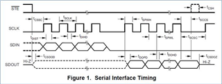
spi.mode = 0b01 #mode 1 du SPI i.e. polarite = 0, phase = 1 => mode 1 (Cf. datasheet AFE, spi timing)

## FONCTIONS  -----------------------------------------------------------

# Protocole des donnees vers les registres de l'AFE (Cf. pages 17-19 datasheet AFE):

    # Le paquet de bits a envoyer est compose de 24 bits (donc 3 octets):
    # Le premier octet correspond a l'adresse du registre sollicite
    # Les deux octets suivants contiennent les valeurs a transmettre sur le registre

def writeRegister(adress,data): # adress: adresse du registre dans lequel on souhaite ecrire
                                # data: donnees a transmettre dans le registre
    adress = adress & 0x1F

    firstByte = data >> 8 # premier octet des data
    secondByte = data & 0xFF# deuxieme octet des data

    spi.writebytes([adress, firstByte, secondByte])

# Lecture des donnees renvoyees par les registres de l'AFE (Cf. pages 17-19 datasheet AFE)

def readRegister(adress,data):

    adress = adress & 0x1F # derniers 5 bits de l'adresse
    adress = adress | 0x20 # permet d'etre en mode lecture (le bit 21 doit valoir 1)

    firstByte = data >> 8
    secondByte = data & 0xFF

    a=spi.xfer2([adress, firstByte, secondByte])
    print("adresse: ")
    print(a)
    print("\n")

def readData(frequence):


    # 1) Envoyer signal a une frequence donnee

    writeRegister(BCM_DAC_FREQ,frequence) # preparer le registre BCM_DAC_FREQ pour une mesure a une freq donnee
    wiringpi.delay(5)

    # 2) Mode lecture de ADC_RESULT

    readRegister(ADC_DATA_RESULT,0x00)

def setupAFE():

    # Initialisation AFE

    writeRegister(ADC_CONTROL_REGISTER1,0x5140)
    writeRegister(MISC_REGISTER1,0x0000)
    writeRegister(MISC_REGISTER2,0xFFFF)
    writeRegister(DEVICE_CONTROL1,0x6004)
    writeRegister(ISW_MUX,0x0000)
    writeRegister(VSENSE_MUX,0x0000)
    writeRegister(IQ_MODE_ENABLE,0x0000)
    writeRegister(WEIGHT_SCALE_CONTROL,0x0000)
    writeRegister(BCM_DAC_FREQ,0x0040)
    writeRegister(DEVICE_CONTROL2,0x0000)
    writeRegister(ADC_CONTROL_REGISTER2,0x0011)
    writeRegister(MISC_REGISTER3,0x0030)

    wiringpi.delay(5)

    # Initialisation des registres de BodyComposition

    writeRegister(ADC_CONTROL_REGISTER1,0x4140)
    writeRegister(MISC_REGISTER1,0x0000)
    writeRegister(MISC_REGISTER2,0xFFFF)
    writeRegister(DEVICE_CONTROL1,0x6004)
    writeRegister(ISW_MUX,0x0408)
    writeRegister(VSENSE_MUX,0x0804)
    writeRegister(IQ_MODE_ENABLE,0x0000)
    writeRegister(WEIGHT_SCALE_CONTROL,0x0000)
    writeRegister(BCM_DAC_FREQ,0x0040)
    writeRegister(DEVICE_CONTROL2,0x0000)
    writeRegister(ADC_CONTROL_REGISTER2,0x0063)
    writeRegister(MISC_REGISTER3,0x0030)

# Fin de la communication AFE/Raspberry

def endCommunication():
    spi.close()

## FONCTION PRINCIPALE -----------------------------------------------------------------------

# # Apres le reset, les registres de l'AFE sont dans leur etat par defaut, il faut donc les mettre dans leur config initiale

setupAFE()

# Lecture registres

readRegister(ADC_CONTROL_REGISTER1,0x4140)
readRegister(MISC_REGISTER1,0x0000)
readRegister(MISC_REGISTER2,0xFFFF)
readRegister(DEVICE_CONTROL1,0x6004)
readRegister(ISW_MUX,0x0408)
readRegister(VSENSE_MUX,0x0804)
readRegister(IQ_MODE_ENABLE,0x0000)
readRegister(WEIGHT_SCALE_CONTROL,0x0000)
readRegister(BCM_DAC_FREQ,0x0040)
readRegister(DEVICE_CONTROL2,0x0000)
readRegister(ADC_CONTROL_REGISTER2,0x0063)
readRegister(MISC_REGISTER3,0x0030)

# Lecture impedance

F = [0x0032, 0x0064] # liste des frequences des courants envoyes (50 kHz, 100 kHz)

for f in F:
    readData(f)

endCommunication()
And I am copying the lines of this code that are the most interesting (writing and reading registers).
def writeRegister(adress,data): # adress: adresse du registre dans lequel on souhaite ecrire
                                # data: donnees a transmettre dans le registre
    adress = adress & 0x1F

    firstByte = data >> 8 # premier octet des data
    secondByte = data & 0xFF# deuxieme octet des data

    spi.writebytes([adress, firstByte, secondByte])

# Lecture des donnees renvoyees par les registres de l'AFE (Cf. pages 17-19 datasheet AFE)

def readRegister(adress,data):

    adress = adress & 0x1F # derniers 5 bits de l'adresse
    adress = adress | 0x20 # permet d'etre en mode lecture (le bit 21 doit valoir 1)

    firstByte = data >> 8
    secondByte = data & 0xFF

    a=spi.xfer2([adress, firstByte, secondByte])
    print("adresse: ")
    print(a)
    print("\n")

def readData(frequence):


    # 1) Envoyer signal a une frequence donnee

    writeRegister(BCM_DAC_FREQ,frequence) # preparer le registre BCM_DAC_FREQ pour une mesure a une freq donnee
    wiringpi.delay(5)

    # 2) Mode lecture de ADC_RESULT

    readRegister(ADC_DATA_RESULT,0x00)
Could you please check if there is an error in this code?
If it's correct, it is possible that the AFE is burnt out, in this case, do you have a program and a circuit in order to check this hypothesis?
Kind regards.
Maxime


