This thread has been locked.

If you have a related question, please click the "Ask a related question" button in the top right corner. The newly created question will be automatically linked to this question.

ADS131M04: Device not responding to configuration change

Part Number: ADS131M04


Hi,

I have a ADS131M04 in the evaluation board and it seems that is not respondig to the configuration change.

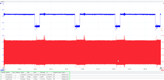
I change the OSR inside the CLOCK register and it doesn't change the time between DRDY(high to low). After I write the register I read it and I can see that the value in the register is the one I set.

Also I am setting the SYNC/RESET signal down for 2ms with a CLKIN of 8MHz and the reset is not doing anything. After the RESET the device is not returning the 0xFF24 and the device continues in LOCK status.

Apart from that the ADC data I receiving is all zeros, the frame I am receiving is "81 00 00 00 00 00 00 00 00 00 00 00 00 00 00 b4 2d 00" with a word size of 24bits. The CRC is correct but I don't understand why all the values are 0.

Do you know what could be happening?

Regards,

Iñaki

  • Hello Iñaki,

    Thank you for your post and welcome to our forum. 

    I am actually working with your local TI support team already via an internal thread. If you would like to continue the discussion here on the external forum, that's also ok.

    Can you share a scope capture or logic analyzer reading of the first frame following the reset pulse? In step 6, where you send the RREG command to read the STATUS register, there will be a response on DOUT in the same frame. This response should contain the 0xFF24 response word, assuming that is the first communication after the reset pulse.

    Instead of the RREG command, you could simply send the NULL command in step 6 and capture the SPI frame. We would want to see /RESET, /CS, SCLK, DIN, DOUT and verify the reset has occurred correctly before proceeding to read/write registers.

    Best regards,

    Ryan

  • Hello Ryan,

    If it's faster I would prefer to do it from here.

    I cannot send you a capture right now.

    I actually I am sending the NULL command after the reset, and only see the 0xFF24 if I have made a hard reset(removing power). When there is no hard reset I get the STATUS value.

    What about the zeros in the ADC data and the no change in the /DRDY time when I change the OSR?

    Regards,

    Iñaki

  • Hi Iñaki,

    All forms of reset, including pin reset, RESET SPI command, and power-on reset (POR), should produce the ready word in the next frame (0xFF24). If you do not see this ready word after sending the SPI RESET command, it means that the command was not latched. Usually this happens when customers do not send a complete frame. Only the RESET command requires the full frame to be latched; other commands are latched immediately following the command word. If the command word is sent but the frame is not completed, you should receive 0x0011 as the next response word.

    This device powers up and begins generating conversion data as soon as master clock is provided. It is not locked after power-up (meaning you do not need to send UNLOCK); however, the device will not respond to any commands until /DRDY transitions from low to high, indicating that POR is complete.

    Please share a capture of the reset command and response in the next frame.

    Regards,

    Ryan

  • Hi Ryan,

    Reset signal(blue), down for 2ms:

    Reset signal (blue) of 2ms

    Time between RESET high to /CS:

    Data from the ADC after the reset and NULL command

    CS -> red

    SCLK -> yellow

    DOUT -> green

    DIN -> blue

  • Hello Iñaki,

    Thanks for the scope images. 

    I'm still not yet sure what the issue may be. It looks like you are pulsing the reset pin with the proper timing. What is the state of /DRDY when the /RESET pin is pulsed? I assume the supplies have fully ramped at this point. It would be helpful to confirm with a scope that /DRDY transitions from low to high after supplies ramp and before the /RESET pin is pulsed.

    I will also loop in some team members internally to see if they have other suggestions.

    Best regards,

    Ryan

  • Hello Ryan,

    Thanks for you reply.

    Here you can see the /DRDY(green) when the RESET(blue) signal is changed. Note that I have moved down a bit the Y axis of the /DRDY signal.

    Regards,

    Iñaki

  • Hello Ryan,

    Apart from the reset issue I would like to check the other problems I have seen.

    1. All ADC data is 0: The STATUS word and the CRC are correct but all the ADC measurements are 0. I receive the "81 00 00 00 00 00 00 00 00 00 00 00 00 00 00 b4 2d 00" frame. If I calculate the CRC of that frame the value is the same.
    2. Changing the OSR in CLOCK register doesn't change anything. I change the register value before applying a 4MHz clock to the ADS131M04. In the images below you can see (inside the green box) that the DRDY freq don't change with different OSRs. Is it normal to have around 1.5 volts in the low part of the DRDY?

    DRDY in blue and CLKIN in red. OSR = 16256

    DRDY in blue and CLKIN in red. OSR = 256

    Regards,

    Iñaki

  • Hi Iñaki,

    It looks like something is loading the /DRDY pin and preventing it from reaching a true logic low level (max V_OL is 0.2*DVDD = 660 mV). Can you share a portion of the schematic showing all connections to the ADS131M04? The only issue this would cause is your microcontroller may miss the /DRDY = low interrupt.

    STATUS = 0x8100 indicates that the device is locked, so the UNLOCK command (0x0655) must be sent before configuring the device registers and changing the OSR.

    I want to reiterate that following any device reset (SPI command or /RESET pin pulse), the reset response word (0xFF24) is only given once in the frame immediately following the reset. All of the subsequent frames will contain the response based on the command in the previous frame. STATUS is the response to the NULL command, so if you are sending SCLKs after reset, you may be clocking out the reset response word without actually reading it in your microcontroller.

    Eric has scheduled a call for us tomorrow to discuss this further. I look forward to talking with you then.

    Regards,

    Ryan

  • Hi Ryan,

    We are connecting one of our meters to the ADS131M04EVM. This are the modifications we have made in the evaluation board:

    • Remove R45
    • Shortcircuit DVDD with AVDD
    • Get DVDD and AVDD from 3v3 external source
    • Unplug JP9
    • Unplug any JP6 Jumper for isolate Clock generation
    • Get Clock source from the microcontroller(8MHz)
    STATUS = 0x8100 indicates that the device is locked, so the UNLOCK command (0x0655) must be sent before configuring the device registers and changing the OSR.

    I aware of this, but the device is LOCKed because the RESET is not working. When I change the OSR the device is not locked.

    I want to reiterate that following any device reset (SPI command or /RESET pin pulse), the reset response word (0xFF24) is only given once in the frame immediately following the reset. All of the subsequent frames will contain the response based on the command in the previous frame. STATUS is the response to the NULL command, so if you are sending SCLKs after reset, you may be clocking out the reset response word without actually reading it in your microcontroller.

    This is what I'm doing, but device only returns 0xFF24 when power put down and restored.

    We will clarify in the call.

    Regards,

    Iñaki

  • Hi Ryan,

    I can confirm that after applying a correct signal on CLKIN all the issues are fixed.

    1. The RESET is now performed correctly and 0xFF24 is received after it.
    2. Changing the OSR changes the frequency of the /DRDY
    3. ADC data is not all 0
    4. The /DRDY signal goes down to 0V.

    Thanks for all your help.

    Regards,

    Iñaki

  • Iñaki - thank you for the update and for your time on the call today. I'm glad the resolution was simple in the end. 

    In summary - while the interface was working properly, you found that the external master clock (MCLK) was not actually reaching the CLKIN pin of the ADS131M04. This caused the interface to remain locked after reset and prevented you from reading any conversion data or change the registers. The /RESET pulse relies on a setup/hold timing requirement in relation to CLKIN in order to execute, which is why the reset response was not received.

    Please let us know if you have any future questions.

    Regards,

    Ryan