This thread has been locked.

If you have a related question, please click the "Ask a related question" button in the top right corner. The newly created question will be automatically linked to this question.

DAC53701: Generating medical Audio and visual alarm

Part Number: DAC53701

Hello Team TI,

Can anyone help me generating medical alarm from this Smart DAC. I tried hard but couldn't get it working.

Please give me I2C code for configuration of this chip to generate Medical Visual and Audio alarm using GPI Pin.

Also please suggest the circuit diagram that can be used for this purpose.

Thanks and Regards,

Deepak Kumar,

Embedded Design Engineer,

Noccarc Robotics Pvt Ltd.

  • Hi Deepak,

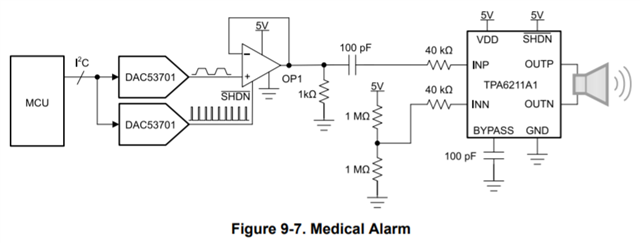
    A circuit is given for the audio medical alarm generation in section 9.2.3 of the DAC53701 datasheet. It uses 2 DAC53701s to create the medical alarm and a pulse frequency.  

    Where were you running into trouble? I will check and see if we also have a visual medical alarm circuit available. The I2C code would be as follows:

    #define I2C_ADDR_DAC1 0x48

    #define I2C_ADDR_DAC2 0x49

    #define I2C_ADDR_BROADCAST 0x47


    //Set up I2C address for DAC1 and DAC2

    //Set GPI pins to 0 for both devices

    //Set GPI_CONFIG in the CONFIG2 register to 111b

    Wire.beginTransmission(I2C_ADDR_BROADCAST);
    Wire.write(byte(0xD2)); // CONFIG2 Register
    Wire.write(byte(0x31)); // Set GPIO_CONFIG to 0b111
    Wire.write(byte(0x00)); // 
    Wire.endTransmission(); // stop transmitting


    // Set GPI_EN in the TRIGGER register to 1b

    Wire.beginTransmission(I2C_ADDR_BROADCAST);
    Wire.write(byte(0xD3)); // TRIGGER Register
    Wire.write(byte(0x04)); // Set GPIO_EN to 0b1
    Wire.write(byte(0x00)); // 
    Wire.endTransmission(); // stop transmitting


    //Set the GPI pin to logic HIGH for the device that needs to be configured (DAC2)

    //Write data to SLAVE_ADDRESS bit field in the CONFIG2 register. Only the device with GPI pin logic HIGH updates the SLAVE_ADDRESS setting passed in the command. Make sure that the rest of the devices on the same I2C bus have their respective GPI pins set to logic LOW during this process.

    Wire.beginTransmission(I2C_ADDR_BROADCAST);
    Wire.write(byte(0xD2)); // CONFIG2 Register
    Wire.write(byte(0x40)); // Set SLAVE_ADDRESS to 0b01
    Wire.write(byte(0x00)); // 
    Wire.endTransmission(); // stop transmitting


    //Toggle the GPI pin of the device bring programmed to logic LOW

    //Set GPI_EN to 0b

    Wire.beginTransmission(I2C_ADDR_BROADCAST);
    Wire.write(byte(0xD3)); // TRIGGER Register
    Wire.write(byte(0x00)); // Set GPIO_EN to 0b0
    Wire.write(byte(0x00)); // 
    Wire.endTransmission(); // stop transmitting


    // Change GPI_CONFIG to 000b

    Wire.beginTransmission(I2C_ADDR_BROADCAST);
    Wire.write(byte(0xD2)); // CONFIG2 Register
    Wire.write(byte(0x00)); // Set GPIO_CONFIG to 0b000
    Wire.write(byte(0x00)); // 
    Wire.endTransmission(); // stop transmitting 


    //Trigger NVM write operation.

    Wire.beginTransmission(I2C_ADDR_BROADCAST);
    Wire.write(byte(0xD3)); // TRIGGER Register
    Wire.write(byte(0x00)); // 
    Wire.write(byte(0x10)); // Set NVM_PROG to 0b1
    Wire.endTransmission(); // stop transmitting 


    //Power-up DAC1, enable VDD reference, SLEW_RATE: 1.6384 ms (Square wave frequency: 610 Hz)

    Wire.beginTransmission(I2C_ADDR_DAC1);
    Wire.write(byte(0xD1)); // GENERAL_CONFIG Register
    Wire.write(byte(0xC1)); // 
    Wire.write(byte(0x00)); // 
    Wire.endTransmission(); // stop transmitting


    //Set MARGIN_HIGH on DAC1

    Wire.beginTransmission(I2C_ADDR_DAC1);
    Wire.write(byte(0x25)); // DAC_MARGIN_HIGH Register
    Wire.write(byte(0x0F)); // 
    Wire.write(byte(0xFC)); // 
    Wire.endTransmission(); // stop transmitting

      
    //Set MARGIN_LOW on DAC1

    Wire.beginTransmission(I2C_ADDR_DAC1);
    Wire.write(byte(0x26)); // DAC_MARGIN_LOW Register
    Wire.write(byte(0x00)); // 
    Wire.write(byte(0x00)); // 
    Wire.endTransmission(); // stop transmitting

      
    //Set DAC1 GPIO to trigger square wave

    Wire.beginTransmission(I2C_ADDR_DAC1);
    Wire.write(byte(0xD2)); // CONFIG2 Register
    Wire.write(byte(0x18)); // Set GPIO_CONFIG to 0b011
    Wire.write(byte(0x00)); // 
    Wire.endTransmission(); // stop transmitting

      
    //Power-up DAC2, enable VDD reference
    //CODE_STEP: 8 LSB, SLEW_RATE: 204.8 µs x 1.75 = 358.4 µs (Envelope rise/fall times for full-scale:~26 ms)

    Wire.beginTransmission(I2C_ADDR_DAC2);
    Wire.write(byte(0xD1)); // GENERAL_CONFIG Register
    Wire.write(byte(0x0A)); // 
    Wire.write(byte(0x80)); // 
    Wire.endTransmission(); // stop transmitting

      
    //OPTION-1: Configure DAC2 GPIO to trigger low-priority alarm with minimum time settings and trigger

    //Set GPI_CONFIG in the CONFIG2 register to 111b

    Wire.beginTransmission(I2C_ADDR_DAC2);
    Wire.write(byte(0xD2)); // CONFIG2 Register
    Wire.write(byte(0x30)); // Set GPIO_CONFIG to 0b110
    Wire.write(byte(0x00)); // 
    Wire.endTransmission(); // stop transmitting

      
    //OPTION-2: Configure DAC2 GPIO to trigger medium-priority alarm with minimum time settings and trigger
    Wire.beginTransmission(I2C_ADDR_DAC2);
    Wire.write(byte(0xD2)); // CONFIG2 Register
    Wire.write(byte(0x28)); // Set GPIO_CONFIG to 0b101
    Wire.write(byte(0x00)); // 
    Wire.endTransmission(); // stop transmitting

      
    //OPTION-3: Configure DAC2 GPIO to trigger high-priority alarm with minimum time settings and trigger
    Wire.beginTransmission(I2C_ADDR_DAC2);
    Wire.write(byte(0xD2)); // CONFIG2 Register
    Wire.write(byte(0x20)); // Set GPIO_CONFIG to 0b100
    Wire.write(byte(0x00)); // 
    Wire.endTransmission(); // stop transmitting

      
    //Set MARGIN_HIGH on DAC2

    Wire.beginTransmission(I2C_ADDR_DAC2);
    Wire.write(byte(0x25)); // DAC_MARGIN_HIGH Register
    Wire.write(byte(0x0F)); // 
    Wire.write(byte(0xFC)); // 
    Wire.endTransmission(); // stop transmitting

      
    //Set MARGIN_LOW on DAC2
    Wire.beginTransmission(I2C_ADDR_DAC2);
    Wire.write(byte(0x26)); // DAC_MARGIN_LOW Register
    Wire.write(byte(0x00)); // 
    Wire.write(byte(0x00)); // 
    Wire.endTransmission(); // stop transmitting


    // Set GPI_EN in the TRIGGER register to 1b

    Wire.beginTransmission(I2C_ADDR_BROADCAST);
    Wire.write(byte(0xD3)); // TRIGGER Register
    Wire.write(byte(0x04)); // Set GPIO_EN to 0b1
    Wire.write(byte(0x00)); // 
    Wire.endTransmission(); // stop transmitting


    //Trigger NVM write operation.

    Wire.beginTransmission(I2C_ADDR_BROADCAST);
    Wire.write(byte(0xD3)); // TRIGGER Register
    Wire.write(byte(0x00)); // 
    Wire.write(byte(0x10)); // Set NVM_PROG to 0b1
    Wire.endTransmission(); // stop transmitting 


  • Hi Katlynne,

    Thanks for the reply.

    Yes it is giving 610Hz Square wave and LOW,MED,High priority alarm.

    One more question, does medical alarm only compose of only 1 frequency?

  • Hi Deepak,

    I took this screenshot from the blog we have titled Demystifying medical alarm designs, part 1: IEC60601-1-8 standard requirements 

    The frequency can be changed as long as it fits within the IEC standards mentioned. 

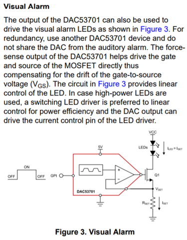
    The schematic for a visual alarm is given in our app note titled Demystifying Medical Alarm Designs With Smart DACs. It's recommended that the visual alarm uses a different DAC53701 from the auditory alarm circuit. If the LEDs are high power, the DAC output can drive the current limit pin of an LED driver instead. 

    Best,

    Katlynne Jones

  • Thanks for the reply,

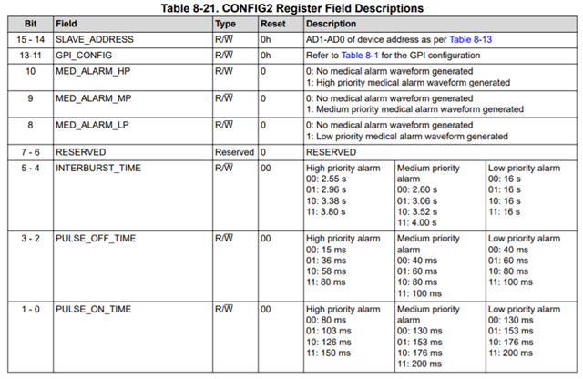
    How can I change 

    1. INTERBURST_TIME 

    2. PULSE_OFF_TIME

    3. PULSE_ON_TIME

  • Hi Deepak,

    These can be changed in the CONFIG2 register (0xD2). The timing will be specific to the type of alarm that is enabled in the GPIO_CONFIG field: 

    Modify the data written to the CONFIG2 register with the desired times. This example sets the settings to the maximum for a low-priority alarm: 

    //OPTION-1: Configure DAC2 GPIO to trigger low-priority alarm with maximum time settings and trigger

    //Set GPI_CONFIG in the CONFIG2 register to 110b, Set INTERBURST_TIME, PULSE_OFF_TIME, PULSE_ON_TIME to 0b11

    Wire.beginTransmission(I2C_ADDR_DAC2);
    Wire.write(byte(0xD2)); // CONFIG2 Register
    Wire.write(byte(0x30)); // Set GPIO_CONFIG to 0b110
    Wire.write(byte(0x1F)); //  Set INTERBURST_TIME, PULSE_OFF_TIME, PULSE_ON_TIME to 0b11
    Wire.endTransmission(); // stop transmitting

    Best,

    Katlynne Jones