This thread has been locked.

If you have a related question, please click the "Ask a related question" button in the top right corner. The newly created question will be automatically linked to this question.

ADS8588S: Sampling rate issue

Part Number: ADS8588S


Dear,


I am making the DA measure system by ADS8588S chip.

But, I had some problem for sampling rate, please advice this problem


[Test status]

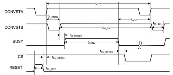
used driver : ad7606.c / ad7606.h / ad7606_spi.c  in kernel's default driver

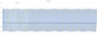
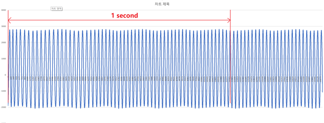
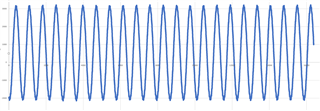
input test signal : 60Hz signal


expect result : As you know, the 60Hz signal is  the 60ea sine signal  per 1 sec like below picture.
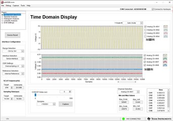
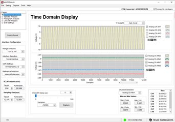
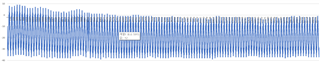
my result 

      It's my result.  

      It's JUST 23ea sine signal per 1 sec like below picture.

      please, let me know what to change for 60ea sine signal per 1 sec.

best regards,

hosung shin.


  • Hi hosung,

    What's your actual sampling rate on ADS8588S? Can you please provide your timing for CONVST, BUSY, /CS captured with a scope for more than two cycles? also your original raw data from the ADC will be helpful to check. Thanks.

    Regards,

    Dale 

  • Hi Dale,

    We want you to use the 16KSPS .

    I attached the raw data's excel file  ( testresult1.xlsx )

    As our excel, the colume A is 1 channel data.  also, it's the 60hz signal.

    ( other channels ( B ~ H ) is a dummy values )

    And, we will provide our captured timing ( CONVST, BUSY, CS) when ready.

    best regards,

    hosung shin.

    testresult1..xlsx

  • Hi hosung,

    Are you configuring OSR through OS0/OS1/OS2 pins for using oversampling feature? 

    Best regards

    Dale

  • Hi Dale,

    We used the OS0=0, OS1=0, OS2=1 ( OS RATIO = 2 ).  >> it's the default value in 7606 driver.

    Also, this results are a same when we changed the OS0=0, OS1=1, OS2=0 /  OS0=0, OS1=1, OS2=1 / the OS0=1, OS1=0, OS2=0 

    best regards,

    hosung shin.

  • Hi hosung,

    When the hardware pin OS0=0,OS1=0 and OS2=1, your OSR is 16 not 2. When OS=1,OS1=0 and OS2=0, the OSR is 2. 

    When your OSR is 16, the maximum throughput is limited to 200ksps/16=12.5ksps, you will not be able to achieve 16ksps data rate.

    When your OSR has a different configuration, you should check different number samples to see how many cycles in one second. For example, for 60Hz sinewave input signal:

    When OSR is 0 (OS0=0,OS1=0 and OS2=0) and the data rate is 16ksps, you should check 16k sample codes and you should be able to see 60 sinewave cycles in one second, see the 1st screenshot below which was captured on the EVM.

    When OSR is 16 (OS0=0,OS1=0 and OS2=1) and the actual data rate is 12.5ksps, you should check 12.5k sample codes and you should be able to see 60 sinewave cycles in one second. See the 2nd screenshot below.

    When OSR is 64 (OS0=0,OS1=1 and OS2=1) and the actual data rate is 3.125ksps, you should only check 3.125k sample codes and you should be able to see 60 sinewave cycles in one second. See the 3rd screenshot below.

    To make it easy for you to check, I suggest you to configure all three OS pins to low or directly short them to the ground, then check how many cycles you get in one second during 16000 samples for 16ksps data rate.

    Best regards,

    Dale

    OSR=0 (OS0=0,OS1=0 and OS2=0): 

    OSR=16 (OS0=0,OS1=0 and OS2=1): 

    OSR=64 (OS0=0,OS1=1 and OS2=1): 

  • Hi Dale,

    Thanks you for your advise.

    Our result has  84 ea sine signal per 1 sec like below picture.

    [input signal]

    60Hz signal  ( it's a same )

    [It's our changed point]

    we directly short them(all three OS pins) to the ground.

    ( OS0 = 0 / OS1 = 0 / OS2 = 0 )

    [result]

    Our result has  84 ea sine signal per 1 sec.

    >> please, let me know what part can I change to reduce it to 60 ea signals.

    best regards,

    hosung shin.

  • Hi Dale,

    Also,  It's our  timing for CONVST, BUSY, CS captured with a scope. ( attached PDF file )

    8780.ads8588.pdf

    best regards,

    hosung shin.

  • Hi hosung,

    Thanks for following my suggestion and doing the experiment.

    Your actual sampling rate is 11.384ksps, however you are checking the conversion samples from No. 0 to No. 16384 for one second, this is incorrect. When your sampling rate is 11.384ksps, the number of sinewave cycles between the sample 0 and sample 11384 should be checked which are the samples in one second.

    Please see my highlight below for your waveform from the conversion codes, you have ~60 sinewaves in one second.

    Best regards,

    Dale

  • Hi Dale,

    Yes, you are right.

    If the sampling rate is 11.384ksps, it's 60ea sine waves in one second.

    Then, if I want to sampling the 16ksps, it's the OSR is 0 (OS0=0,OS1=0 and OS2=0) 

    Is it  right ?

    Also, If I want to sampling the 4ksps, What is the OSR's value ?

    best regards,

    hosung shin.

  • Hi hosung,

    The sampling rate is controlled by the CONVST signal which is sent from your controller. The OSR pins are used for oversampling. If these OSR pins are  000 (OS0=0,OS1=0 and OS2=0), your actual sampling rate can be set up to 200ksps. If these OSR pins are not 000, your actual sampling rate is limited by the OSR configuration. See the ADS8588S datasheet for the details.

    Best regards,

    Dale 

  • Hi Dale,

    Thanks you for your advice.

    It's my last question.

    Your said means....

    [1] send the CONVST control signal for 16ksps sample rate.

    [2] read data continue..

    [3] send the CONVST control signal for 4ksps sample rate.

    [4] read data continue...

    Is it right?

    best regards,

    hosung shin.

  • Hi hosung,

    No. The sampling rate is determined by the CONVST signal, it's the tcyc (cycle time in the following timing) starting at the rising edge of CONVST and ending at the next rising edge of CONVST. If you want 16ksps sampling rate, your tcyc time should be 62.5us. I suggest you to check the details in datasheet. I hope this helps.

    Best regards,

    Dale