This thread has been locked.

If you have a related question, please click the "Ask a related question" button in the top right corner. The newly created question will be automatically linked to this question.

DAC7750: Iout range calculation

Part Number: DAC7750
Other Parts Discussed in Thread: DAC8750

Hi Team,

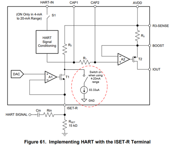
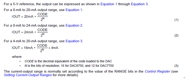
According to the datasheet DAC7750, RANGE bit set R2 and then change the Iout range as shown in the screenshot below.

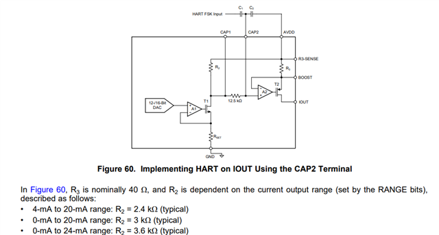
However from the structure shown above, I assume that 


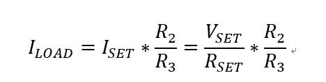
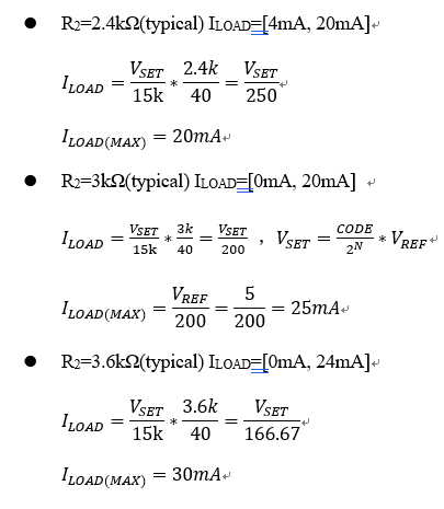
Where the calculation is different from the range in datasheet. 

Questions:

1. Why I have different calculation result with same R2 value?

2. What's the logic behind for equation (1),(2),(3)? Could you please help clarify? 

Thanks.


Best Regards,

Tess Chen

  • Tess, 

    For question 1, I'm not exactly sure about how the DAC is constructed for the 4-20mA range, but it is probably something like this: 

    Here I've drawn it so that the 4mA at the output is an added offset when this range is used (this comes from the gained up 83.33uA switched in for this output range). This way, the DAC range gives the output current from  is from 0 to 16mA, with an added 4mA. 

    Here, the ILOAD = (VSET/RSET + 83.33uA)*(R2/R3)

    Then VSET would be 5V (max) and the scaling resistor R3 is 50Ω instead of 40Ω. Then all the ranges are consistent.

    For 2, the DAC code value sets the output current based on the number of bits of the DAC. For the DAC7750, N is 12, and there are 2^N codes. This would be 4096 for a 12-bit DAC. For the DAC8750, N would be 16 and there would be 65536 codes. 

    Joseph Wu