This thread has been locked.

If you have a related question, please click the "Ask a related question" button in the top right corner. The newly created question will be automatically linked to this question.

RE: ADS124S08EVM: ADS124S08EVM How to make a voltage measurement across a resistor

Other Parts Discussed in Thread: ADS124S08EVM, ADS124S08

Thanks for details.

I have connected resistor @ Pin 1 & pin 2 of J8. 

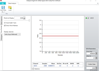
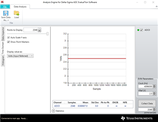
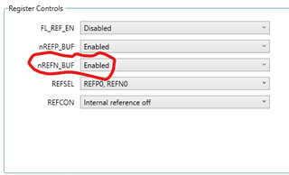
I see below result for register configuration of MUXP = AIN8 and MUXN = AINCOM (or AIN9)

Voltage read was 2.5V. That is correct. But, how to find resistor value (as current source & voltage difference across resistor not available) ?

  • Hi Sadashiva,

    I split your question from the previous thread as the topic has changed.  The measurement you are making with the configuration you are using is not across the resistor but instead you are actually just measuring the reference itself.

    I would suggest taking a look at the ADS124S08EVM user's guide to see the various types of measurements that are capable using the EVM.  The EVM is capable or measuring TC, RTDs (which is a type of resistor measurement), bridge sensors, voltage and current inputs.  Each of these are detailed in the user's guide on how to set up each type of measurement.

    If you give me more specific details on what you want to do, I would be glad to give additional information.

    Best regards,

    Bob B

  • I'm was not full explained in previous query/thread...

    Experiment-1: Just selected MUXP & MUXN manually. Without running script.  Which script to run ?

    I have connected known Resistor, 670 ohm (known value) at pin-1 & pin-2 of J8 connector.

    and connected 22K resistor (value to be calculated) at pin-2 & pin-3. I want to calculate resistor value connected across pin-2 & pin-3

    Register controls in ADC evaluation software GUI:

    MUXP : AIN8

    MUXN: AIN9

    Measured voltage (using multimeter) at pin-1 is 2.5V & at pin-2 is 2.426V. I was expected ADC output code of 16280610 for 2.426V at AIN8 (I have taken full-scale code 16777215 [2^24] for full-scale voltage of 2.5V)

    Mean value read from Data Analysis is 8388607.0. Any reason for wrong value read from ADC ? I want to measure resistance value in this setup only and not in an alternate setup.

    Experiment-2: with "2-wire RTD" script run. This looks fine to me 

    I have connected ~100 ohm across pin-1  & pin-4 of J7

    I'm getting 99.05 ohm by using below formula - 

    RRTD= (2 × R68 × ResultCODES/ PGA ) / (2^24 – 1) 

  • Hi Sadashiva,

    For your first experiment, this would be very similar to the Thermistor Configuration circuit described in the ADS124S08EVM user's guide in section 5.1.2.2 on page 25.  You will notice that Figure 19 is very similar to your experiment.  JP8 is set to VREF at 2.5V, and JP11 is set so that pin 3 of J8 connects to ground.  As AIN9 is now at AGND potential, the PGA must be disabled.  The script that most resembles this measurement is the Thermocouple Measurement on J8 with PGA Bypassed. 

    The full-scale range (FSR) for the ADS124S08 is +/- VREF/GAIN/(2^24 - 1) as the output format is binary 2's complement (with half of the total codes as positive and the other half as negative).  For VREF= 2.5V, the value of one code (LSB) for 2.5V is 2*2.5/1/(16777215) or approximately 298nV.  The approximate code for the 22k resistor would be 2.46V/298nV or 8140305.

    If you are still seeing +FS, then check to make sure that the PGA is disabled/bypassed and the J8-pin3 is connected to AGND via JP11.

    Best regards,

    Bob B

  • Thanks Bob,

    I checked at PGA register settings and noticed that it is disabled by default. So, it is not the root cause for this error. When I checked at Register 0x05 REF, I noticed that nREFN_BUF disabled by default. It started working when I enabled it.

    Thanks for support..!