This thread has been locked.

If you have a related question, please click the "Ask a related question" button in the top right corner. The newly created question will be automatically linked to this question.

TLA2528: Datasheet clarifications

Part Number: TLA2528
Other Parts Discussed in Thread: ADS7128

Hello all,

I recently got back from the fab house our custom PCB that features a couple of TLA2528. Like any other part, before you make a decision whether to use it or not, you take a peek at the datasheet. Well turns out the datasheet for this part was a lazy copy-paste from the ADS7128 or similar product and half the features are not available, at least that's what I'm starting to realize.

This is causing a major delay in the deployment of our company's hardware, not to mention we might have lost a few thousands in the process.

Would someone be able to clarify/fix the datasheet? How does OSR works??  At this point, I can't trust what I'm reading anymore as I'm having issues trying to read values from it.

I'm getting 0 ADC count from 0-5V inputs and 4095 counts from some thermistor ready inputs (10kohm voltage divider to a 3.3V rail) which is what I expected. As soon as I add a sensor to any of the inputs, the ADC counts for the input start to jump all over the place in the full 0 - 4095 range. It doesn't make sense, if the timing of the i2c is wrong, I would expect to get garbage on the inputs with nothing connected to it but I'm getting the expected counts. 

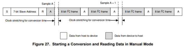
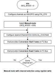
I'm following the manual mode procedure listed below

Anyone can help with this, I will greatly appreciate some insight?

Kamil

  • Hi Kamil,

    Let's start with confirming that the I2C interface is working as expected. Are you able to read address 0x00? On power-up, the BOR bit is set, hence the expected readback value will is 0x81.

    If you are able to read address 0x00 correctly, you can read channel 0 conversion result without needing to write to any registers. Kindly refer to figure 27 in the datasheet -

    Can you kindly test if you are able to read correct conversion result when you are continuously reading only from channel 0?

    For using the OSR mode i.e. Programmable Averaging Filter, you will need to configure the OSR[2:0] register field. When you initiate a conversion, the device internally capture the necessary samples and generate an average result. During this time, SCL will be pulled low by the ADC.

    The line on STATS_EN in the TLA2528 datasheet is an oversight and will be corrected. Thanks for highlighting this.

    Regards,

    Rahul

  • Ok sounds good. I was able to resolve my issue. I completely missed the fact that the response comes as 2 bytes but the last nibble of the LSB was all zeros, I just had to shift the WORD >> 4 and that was it.