This thread has been locked.

If you have a related question, please click the "Ask a related question" button in the top right corner. The newly created question will be automatically linked to this question.

ADS124S08EVM: Enabling Interrupt Mode

Part Number: ADS124S08EVM
Other Parts Discussed in Thread: ADS124S08,

Hi team,

We are going to use ADS124S08 interfacing with STM32F746ZET6 for our RTD application.

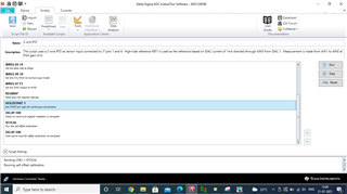
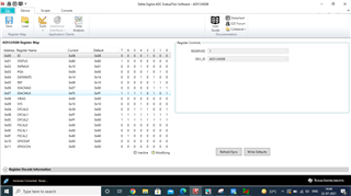
Now we are performing our RTD testing with ADS124S08EVM through GUI.

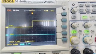
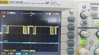
In default GUI scripts you are following polling method for retrieving data, we also confirmed this by probing the DRDY# pin in the EVK kit it is kept low, no transitions are noticed.

In our original application we want to retrieve the data using interrupt method.

Can you please guide me how to enable the interrupt mode in the ADC.

  • Hi Sarumathi,

    There are 2 modes of operation for the ADS124S08 which are single-shot and continuous.  The status of DRDY depends on the mode of operation chosen.  In single-shot mode, the DRDY will only transition high to low once following end of the completed conversion.  In continuous mode, the DRDY will transition high to low each time the conversion completes.  In any mode, when the conversion data are read from the ADS124S08 the DRDY will go back high.  DRDY will also go back high any time you read/write the device.

    The EVM firmware uses an interrupt method set to trigger on the falling edge of DRDY.  The interrupt routine sets an internal flag indicating conversion data are ready to be read from the ADS124S08.  The EVM firmware does not use a direct polling of the DRDY pin, but instead polls the internal flag setting in the main application loop.  If the flag is true, then the data are read.

    This same method works regardless of the mode of operation.  The only difference when using single-shot mode is the START command must be reissued to start another conversion.

    The ADC itself does not have an 'interrupt' mode, but instead uses the falling edge of DRDY to signal a conversion has completed.  DRDY would connect to an interrupt capable GPIO on your processor signaling that a conversion has completed and a new result is available to be read from the ADC.  See Figure 72 in the ADS124S08 datasheet as to the operation of the DRDY signal for both single conversion and continuous conversion modes.

    Best regards,

    Bob B

  • Hi Bob,

    Thanks for the response.

     "The EVM firmware does not use a direct polling of the DRDY pin, but instead polls the internal flag setting in the main application loop" : Can you please tell me by which flag or register setting we can achieve this?

    More over we have probed the DRDY pin with oscilloscope. There is no transition noticed(low to high or high to low). It is kept low.

  • Hi Sarumathi,

    The default startup for the ADS124S08 is continuous conversion mode.  However unless the START command is issued DRDY will not make the high to low transition.  There is also the START pin that supersedes the START/STOP commands.  Take a look at the Operating Flow Chart Figure 82 in the ADS124S08 datasheet on page 58.  Also review the discussion in section 9.4.4.  

    So you will either need to set the START pin high (not floating) or use the START command to start conversions.  After that you should see the DRDY toggle at the end of the conversion.  If not, then make sure all supplies (DVDD, IOVDD and AVDD/AVSS) are nominal, and the RESET pin is high (not floating).

    As far as the flag setting, this is a firmware flag and has nothing to do with the ADS124S08 itself.  As pseudo type code I would have a boolean similar to as follows:

    main()

    {

            bool fDRDY = false;

            // ..... normal start up code

            //....main loop

            while(.t.) {;

                if(fDRDY)

                {

                    // Read the conversion data

                    fDRDY = false;

                }

            //....end of main loop

            }

    }

    interrupt function DRDYdetected() // Some interrupt function that recognizes falling edge of DRDY

    {

            fDRDY = true;

    }

    Hope that helps.

    Best regards,

    Bob B

  • Hi Bob,

    I am running the default the script for 2-wire RTD.

    That script itself providing START command. Please look into the below snap for the script reference.

    And I have probed the START and DRDY pins. START goes high when it was sending through command after that it kept high only. While the DRDY is kept low only. Please refer the below snap.

    After the conversion also the DRDY is kept low.

    As you suggested I have checked the voltage level of DVDD, IOVDD and AVDD/AVSS. I didn't find any issue with the voltage levels.

    DVDD= 3.23V

    IOVDD = 4.99V

    Is there any external pull down/pull up option need to be given for DRDY pin?

    Awaiting for your reply.

  • Hi Sarumathi,

    This thread started out trying to connect the ADS124S08EVM to an external processor.  Now it would appear that you are using the onboard EVM processor and the EVM GUI.  So I'm somewhat confused as to what you are trying to do.  In your last post you said IOVDD is 4.99V.  Did you mean AVDD?  IOVDD for the ADS124S08EVM would normally be 3.3V.

    The DRDY pin is an always active push-pull output pin.  So no, there is no pullup or pulldown required. 

    Did you make any modifications to the EVM that might be interfering with the operation?  Have you probed the RESET?  This pin must be high for device operation and not floating or low.

    When running the script, have you verified that the communication to the ADC is working by verifying that the register contents are changing to the appropriate values.  Have you actually tried to collect data?

    Best regards,

    Bob B

  • Hi Bob,

    Our plan is to interface ADS124S08EVM with STM32F746ZET6. But before that we want to verify/test the functionality of the ADC with its EVK.

    So now we are doing our test with ADS124S08EVM. We are using 0.1% tolerance 143ohm as RTD in 2 -wire RTD configuration and I am running the default 2-wire RTD script. While running the script the register values are changes to their appropriate values and I can able to collect data also. Please look in to the below image for your reference.

     In your last post you said IOVDD is 4.99V.  Did you mean AVDD?  IOVDD for the ADS124S08EVM would normally be 3.3V.---> For this i did mistake in my previous post. Please find the correct value below

    IOVDD and DVDD = 3.23V

    AVDD = 4.99V

    Did you make any modifications to the EVM that might be interfering with the operation?  Have you probed the RESET?  This pin must be high for device operation and not floating or low.----> No. I didn't make any modification to EVM. I have gone through the EVM user guide and verified that all the jumper setting are installed as per the guide. And I have probed the RESET pin it is in high state(3.3V) only.

  • Hi Sarumathi,

    The configuration appears to make sense to me and the code returned is in line with the resistor value you are using.  However I would expected to see some code variation and not just one code value due to ADC noise.  Can you collect a series of at least 128 samples to see if there is variation?

    Going back to your initial questions regarding DRDY, if the START pin is high and the Mode bit setting is the default value (continuous conversion mode) then DRDY should toggle at the selected data output rate.  When not reading the conversion data, DRDY will appear as mostly low, but should toggle low-high-low when conversion completes.  At 20sps you should see the pulse every 50ms.  Make sure that the time base setting on the scope is set to capture the pulse every 50ms.  Verify that you see this pulse.

    Best regards,

    Bob B