This thread has been locked.

If you have a related question, please click the "Ask a related question" button in the top right corner. The newly created question will be automatically linked to this question.

ADS4249EVM: New ADS4249EVM is abnormal, and the cdce72010 is very hot

Part Number: ADS4249EVM
Other Parts Discussed in Thread: CDCE72010, ADS4249

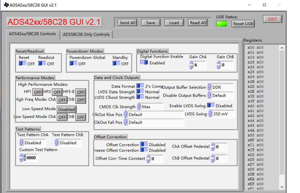
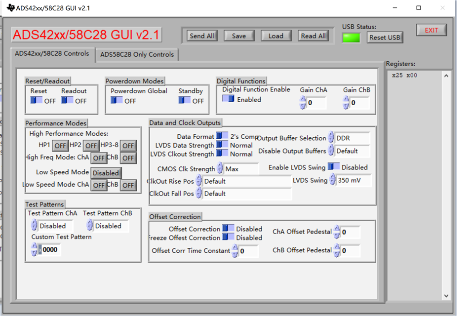
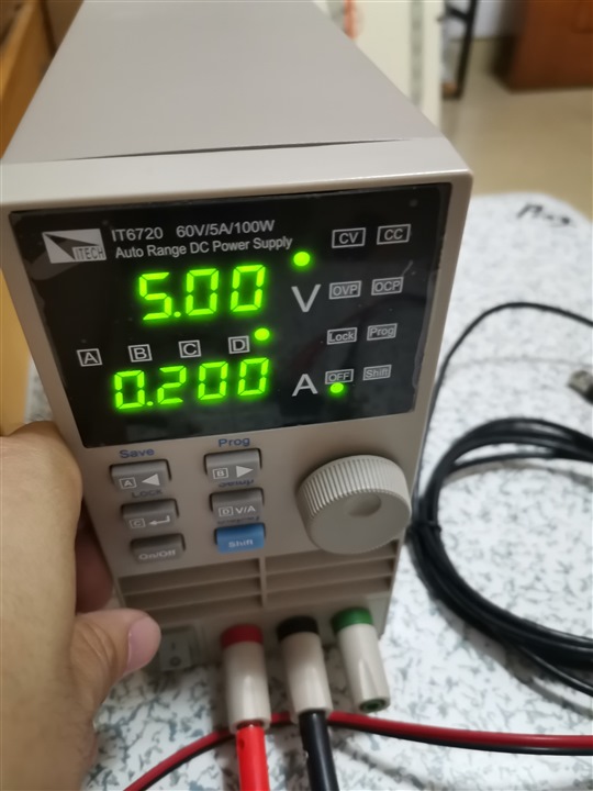
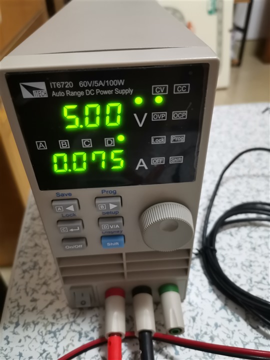
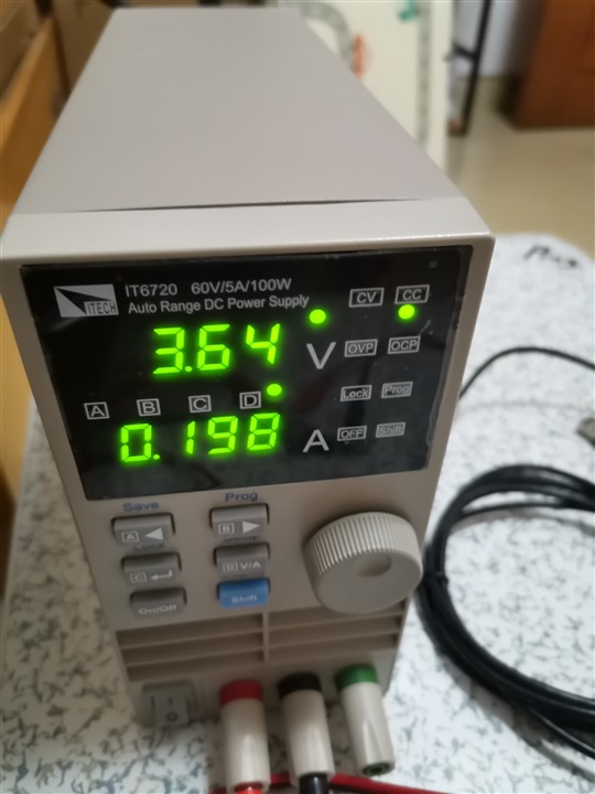
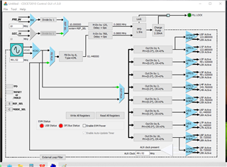
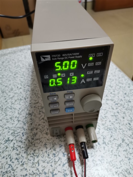
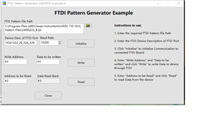
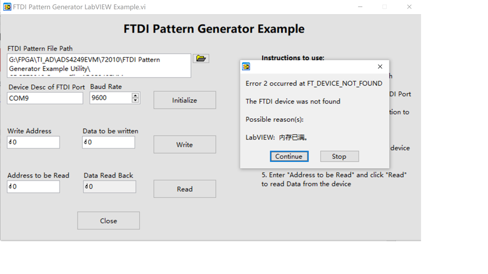
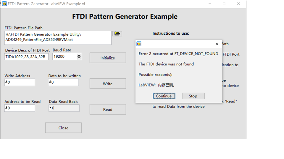
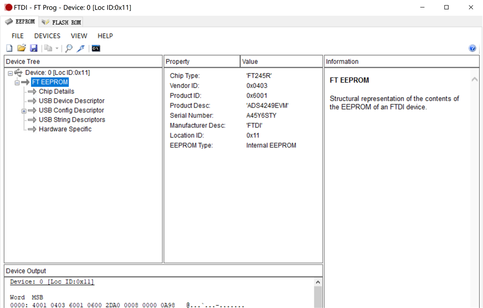
Hello, I bought ads4249evm in Ti mall with order No. t0512046. When powered on, it was found that cdc72010 was very hot and the USB connection could not be recognized(ADS42xxx SPI GUI (Rev. B) and CDC72010 GUI). The measured + 5V displayed 5.2v, + 1.8va and + 1.8vd displayed 1.7V, + 3.3V_ CLK displays 3.23v and the voltage is normal. How to solve the problem. The jumper is factory set and has been checked with the user manual.thank you.

  • Hi Guantao,

    Can you provide me with the current draw of the EVM once powered on?

  • Hi Guantao,

    Can you download and install the program FT_Prog and verify that the FTDI chip is being recognized by the PC as ADS4249EVM?

    If the Product Description does not show ADS4249EVM, then you will have to reprogram the FTDI chip. Instructions to do this are below.

    First, open FT Prog and press the magnifying glass to scan for connected devices. If multiple devices are connected, please disconnect everything except for the ADS4249EVM. This will ensure that only the correct EVM is being written to.

    Right click on the FT EEPROM and select Apply Template -> From File and browse to the ADS42xx_FTDI_Template.xml file. It should be attached here:

    4846.ADS42xx_FTDI_Template.xml
    <?xml version="1.0" encoding="utf-16"?>
    <FT_EEPROM>
      <Chip_Details>
        <Type>FT245R</Type>
      </Chip_Details>
      <USB_Device_Descriptor>
        <VID_PID>0</VID_PID>
        <idVendor>0403</idVendor>
        <idProduct>6001</idProduct>
        <bcdUSB>USB 2.0</bcdUSB>
      </USB_Device_Descriptor>
      <USB_Config_Descriptor>
        <bmAttributes>
          <RemoteWakeupEnabled>true</RemoteWakeupEnabled>
          <SelfPowered>false</SelfPowered>
          <BusPowered>true</BusPowered>
        </bmAttributes>
        <IOpullDown>false</IOpullDown>
        <MaxPower>90</MaxPower>
      </USB_Config_Descriptor>
      <USB_String_Descriptors>
        <Manufacturer>FTDI</Manufacturer>
        <Product_Description>ADS4249EVM</Product_Description>
        <SerialNumber_Enabled>true</SerialNumber_Enabled>
        <SerialNumber />
        <SerialNumberPrefix>A4</SerialNumberPrefix>
        <SerialNumber_AutoGenerate>true</SerialNumber_AutoGenerate>
      </USB_String_Descriptors>
      <Hardware_Specific>
        <HighIO>false</HighIO>
        <D2XX>false</D2XX>
        <ExternalOscillator>false</ExternalOscillator>
      </Hardware_Specific>
    </FT_EEPROM>

    The program will show a message stating the template was successfully applied. You will notice the Product Desc: will have changed to ADS4249EVM.

    Then, follow the below image by first pressing the lighting bolt icon. Ensure that there is only 1 device in the Device List checked with the Product Description labeled as ADS4249EVM. If there is a check in the box numbered as 3 below, untick this check box since we are not programming a blank device. Lastly, press the program button and wait for this to complete.

    Once programming is finished, please unplug the usb cable, close out of FT Prog, reconnect the USB cable, and then re-open FT Prog. The device description should now show ADS4249EVM. Once this is verified, the FTDI programming is completed. You can close FT Prog. Please verify that the Status LED in the GUI turns green.

    Thanks,

    Chase

  • I don't have a tool to test the current. In addition, the temperature of cdce72010 is too high after power on, and my hand can't touch it for a long time. This should be abnormal. J14 is open circuit, cdce72010 should work.

  • Hi,

    When I set the sending parameters through the GUI and read the parameters again. The parameters are not updated. Is this normal?
    Send operation
    Read operation
  • When I try to use the digital adjustable power supply IT6720 to supply power to the EVM, set the 5V output, the current limit is 0.2A, short circuit J14, the output current is 0.075A, then open circuit J14, the output current reaches 0.2A, the voltage drops to 3.64v, and cdce72010 heats.

    Set the power out put

  • Hi Guantao,

    We are experiencing similar issues on our lab's EVM (the CDC gets too hot to touch). With the CDC powered down, the current draw is around 75mA @ 5V. When we open J14, we see the current rise to around 780mA @ 5V. Is it possible for you to raise the current limit to 800mA and report back this value with J14 opened? I believe the voltage drop from 5V down to 3.6V is due to reaching the set current limit.

    Another check, if the reset, power down, or standby mode is toggled on the GUI, does the current drop to a lower value or remain the same? Using these buttons is a good way to verify that the SPI communication is functioning properly.

    Thanks

  • Thanks.I will try it.

  • Can I use cdce72010 GUI SPI to set the parameters? I tried and couldn't connect. In addition, the CDC heat is so high, do I need to add heat sink to cool down?
  • HI,And i found the CDC Operating “temperature range (C)-40 to 85”。Is this high temperature normal now? Does the peripheral circuit cause CDC heating.

  • Hi, ads4249 GUI control is ok. And I raise the current limit to 800mA,the current rise to around 5130mA @ 5V.

  • Hi Guantao,

    I am checking with our clocking team regarding this issue. Please kindly await our response.

    Regards

  • Hi Guantao,

    Sorry for the delay in this response. The high temperature is due to the CDCE72010 being a high power consumption part and operating temperatures in this range is normal for this device. Around 550mA draw is accepted as normal for this EVM. Can you confirm that you are successfully able to configure and capture data using this EVM with an external clock?

    Programming the CDCE using the CDCE72010 specific GUI is not possible. This GUI was for a TI CDCE72010EVM (from 2008) and will not connect to the ADS4249EVM.

    Unfortunately, it appears that programming the CDCE part using the ADS4249EVM GUI is not possible either. This seems to have been an oversight on the designer's part back when this was created. I have attached a standalone utility that TI has offered as a solution in the past. FTDI Pattern Generator Example Utility.zip

  • Thanks,The Labview GUI  "Ftdi pattern file path" select where the file path is? The compressed package contains only three files "ftdi pattern generator example. exe" "ftdi"_ Pattern_ Errors.csv”“FTDI_ Pattern_ Generator.dll”

  • Hi Guantao,

    For future reference, these pattern files are typically found in the installation directory of the EVM GUIC:\Program Files (x86)\Texas Instruments\{EVM FOLDER}\Pattern Files

    However, it appears that the ADS4249EVM does not have a pattern file in this directory, so instead I have created some pattern files from scratch for you. The attached files should allow for reading/writing of both devices on the EVM (ADS4249 and CDCE72010).

    ADS4249EVM_PatternFiles.zip

    Regards

  • Thanks,I found that the GUI could not recognize the serial port device

  • Guantao, thanks for showing these images.

    One suggestion I have is to try it again with the "Device Desc of FTDI Port" set to "ADS4249EVM" and see if this allows you to connect? If not, we can try to look into an alternative solution. Please try this and let us know. 

    Thank you

  • I can connect to cdc72010. Now there are two problems. The first register 0 always reads the value of 0. When I read register 1, I read register 0 again. Each time I read the value is different. The last time I read the value is 0

    The second problem is to read register 1 and write register 1, but the read register value remains unchanged

  • Guantao,

    Does the writing function work successfully? To do this, read the SPI lines, specifically SEN, SCLK, SDATA (mosi) and verify that these match the format in the datasheet for any specific register write. My second question for you is: Is this reading functionality really necessary? Additionally, are you able to configure both parts on the EVM and get successful data captures?

  • I will try it.