This thread has been locked.

If you have a related question, please click the "Ask a related question" button in the top right corner. The newly created question will be automatically linked to this question.

ADS131M06: configured in single ended analog input

Part Number: ADS131M06
Other Parts Discussed in Thread: ADS124S08

Hello Guys,

Good day.

Our customer is designing a board that requires 12 ADC channels, 6 are differential and 6 are single ended. Can the ADS131M06 be configured to support the 6 single-ended ADC channels?

Additionally, do we have a reference design for the ADS131M06 illustrating the ideal power configurations with the designed for components list?

Thanks and regards,

Art

  • Hello Art,

    Can the ADS131M06 be configured to support the 6 single-ended ADC channels?

    The short answer is yes, there's no problem doing this.

    I would like to confirm that the customer understands that they'll lose half of there effective dynamic range using the ADC in a single ended configuration (where AINxN is connected to GND. Puesdo differential is better for this device. TIPL ADC link on input types is listed here: https://training.ti.com/ti-precision-labs-adcs-sar-adc-input-types?context=1139747-1140267-1128375-1139103-1128659 

    If they understand this, then they can skip this explanation below and move onto the next question.

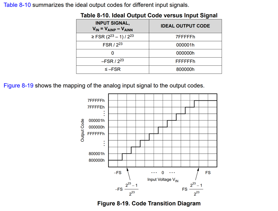
    As shown in the table above, V_IN is determined by V_IN = V_AINP - V_AINN . V_AINP can never be less than V_AINN if V_AINN is connected to GND. Remember, the ADC doesn't lose resolution here, is just the voltage swing is confined to the positive half of the graph which means there's less codes that can differentiate between small changes in voltage.

    Additionally, do we have a reference design for the ADS131M06 illustrating the ideal power configurations with the designed for components list?

    Hmm, not sure what the intent of this question was. My assumption is that we want to talk about the components around the device that help it function.

    The datasheet contain the recommended list of components needed to use the device. In addition, the EVM has the recommended components and some of the 5V -> 3V3 Analog LDO and clock tree circuits that can be used with the device. And finally, you can see an example reference design using a similar part here: https://www.ti.com/tool/TIDA-010036 which has all that and more. At a high level the M04 is the 4 channel version of the M06 but there are some subtleties within the design where this is not the case. For getting a component list and understanding the ecosystem around the device, it will be helpful enough to you.

    Best,

    -Cole

  • Thanks for looking into this Cole. 

    I might direct customer to this forum thread for he has a few other questions regarding the controller and also to explain his use case better.

    Thanks and regards,

    Art

  • Hi Cole, 

    The sensors we are using are the Flexi Force A201 force sensors: https://www.tekscan.com/products-solutions/force-sensors/a201

    If the -Vref or the ground were tied to the negative input channels of the controller, would that mitigate the loss in the dynamic range? 

    I have a few other questions regarding the clock and Reset pin configurations. Could you please provide an email so that I can loop others in? 

    Thank you for your help!  

  • Hey Matt,

    If the info you'll be asking doesn't have sensitive information, we'd prefer if it was publicly available to search here on E2E. On your post, anyone can go can click the More option to reveal a dropdown and turn on reply notifications so anyone can track the conversation. With that said I sent you an email. 

    To answer the first question, let me try to run some numbers of what you're losing, see if that's still okay. Then I can contrast with the work of getting a common mode signal underneath the Flexi Force sensor you have.  

    Best,

    -Cole

  • Hi Cole,

    Sounds good, at this stage. It is fine continuing the discussion on this thread. 

    In terms of the flexi force sensor calculations and common mode configuration, that would be very helpful!  

    Let me know if you require any additional information.

    Thank you very much for your help. 

    -Matt  

  • Hello Matt,

    -Vref... [was] tied to the negative input channels

    There's a bit of depth here and it includes op amp theory. 

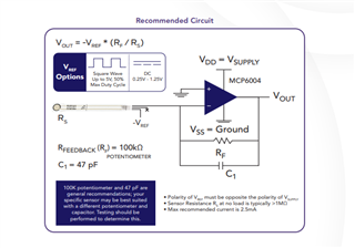
    If we assume you're using the provided MCP6004 circuit, the -VREF's job is to counteract the inverting gain configuration (Vout = -G*Vin for inverting op amp) so the output will be a positive voltage. Because negative supply of the MCP6004 is tied to GND, it can never provide a negative voltage so AINP goes from GND to VDD. If we tied AINN to a negative voltage we're actually making V_IN ( = V_AINP - V_AINN) range more narrow as VIN is even less likely to become a negative number.

    For a high level summary, your goal is to utilize the entirety of the Full Scale Range (FSR) offered by the ADC--which includes the time where V_ANIP swings below V_AINN.

    Funnily enough, if you decided that the negative supply of the MCP6004 was negative (and maybe even tied to the -VREF) you would get a negative voltage applied to V_AINP which could turn V_IN negative if GND was applied to V_AINN, which means your utilizing more of the FSR.

    Would that mitigate the loss in the dynamic range?

    First question is if the loss in dynamic range matters in your application.

    From what I can tell, losing the half of the dynamic range with this ADC resolution is similar to limiting the effective resolution to ~100 of nV. I'm not going to do a noise analysis for MCP6004 in the recommended configuration, but something tells that the error of the amplifier (look at the microvolt level 1/f noise) is already going to contribute more than the effective resolution of the ADC.

    What's the range and resolution of force you actually need to measure for your system? What I was really hoping to find was an easy "resistance to pounds of force" equation in the sensor's datasheet but I could not find it. It looks like Flexiforce offers some help through the guides: https://www.tekscan.com/flexiforce-integration-guides and offers for someone to work with one of their apps engineers. I didn't look much past that and will have to rely on your team to figure that out.

    Is the error you calculated more or less than my rough approximate ~100nV which is just some of the error contributed by the ADC? How about the op amp, is it precise enough to give the performance you want? With that, you can do an error calculation and see if the ADC system is fine or not. Maybe just the op amp needs to be changed.

    Here's some TIPL ADC Error (and noise) training here: https://training.ti.com/ti-precision-labs-adcs-statistics-behind-error-analysis?context=1139747-1140267-1128375-1139104-1128656 and some op amp calculation training here: https://training.ti.com/ti-precision-labs-op-amps-noise-calculating-total-noise?context=1139747-1139745-14685-1138803-13234 . Here's a calculator tool to help as well: https://www.ti.com/tool/ANALOG-ENGINEER-CALC 

    At that point, you can figure out if the whole front end circuit needs to be changed, or just the op amp circuit, or nothing because you met your performance goals.

    Best,

    -Cole

  • Hi Cole,

    Thank you very much for your detailed response. 

    As it terns out, the design that originally included 6 single ended, 6 differential pair inputs will only require 6 single ended inputs to the ADC. The other 6 differential pair inputs are now the inputs of type K thermocouples. 

    Knowing this, this ADC controller will no longer work for our requirements. 

    Do you have any recommendations for a single ended input ADC controller that would work for the FlexiForce sensor? Additionally, any recommendations for a differential input ADC controller that could be used for the thermocouples, one that ideally could handle the cold junction compensation and ADC to SPI output? 

    Thank you for your help, 

     -Matt  

  • I came across the following thread for the ADS124S08:

    https://e2e.ti.com/support/data-converters-group/data-converters/f/data-converters-forum/821587/looking-for-8-10-16-channel-thermocouple-to-digital-converter

    My understanding is that this IC could be used for both in this application (one for each group of 6 sensors),  however the linearization and CJC would have to be performed in software? If that is the case, this thread (from over 2 years ago) references sample code that is in production. Do you have a way of providing me with the sample code if it exists, and if this is a viable solution to accommodate the 12 sensors?  

  • Hey Matt,

    Good find, yes, the ADS124S08 looks like it would work for your application. 

    Yes, CJC would have to be preformed by the MCU or externally but the device at least contains an internal temp sensor to help with the calculation. 

    I idly looked through most of the TIDA (or reference designs) that were listed in that thread you sent and each of the design guides talk about what CJC is and give a high level view of how they do it in software. In addition, that software is provided right now on the TIDA page.

    For example: https://www.ti.com/tool/TIDA-00168 has a firmware section towards the bottom of the page where you can download it here: https://www.ti.com/lit/zip/tidcbv3  The design guide: https://www.ti.com/lit/ug/tidu574/tidu574.pdf talks about it in some detail for section 4.3 using both a device and an RTD do to the measurement. Between all that, you should be able to figure out what the code is doing. 

    This should give you a general starting point. If you do have a question about the code, I suggest you use the orange button up top that says "Ask related question" and reference the TIDA number so it goes to the team that was responsible for the code. If you have a question about the ADS124S08, then you'd do the same thing but use this device number.

    hope this helps.

    Best,

    -Cole