This thread has been locked.

If you have a related question, please click the "Ask a related question" button in the top right corner. The newly created question will be automatically linked to this question.

ADS8681: question about layout

Part Number: ADS8681

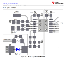
I wonder how to connect AGND and DGND of the ADC using 8 ADCs on one board. The layout example in the datasheet shows two planes (surrounded by dashed lines), I assume these are AGND-plane und DGND-plane which are connected underneeth the ADC. But how to connect the two planes when using 8 ADCs, should the connection between the two planes be layoutet for every ADC or
only one time? From former projects using ADCs (other than ADS8681) I knew that such two planes should be connected together at only one point, not at several points. What ist pls the correct method connecting the planes for more than one ADC on a board? Or Am I totally wrong and only one GND-plane should be used and the connections should be made as suggested in the layout example?

Thx for your advice

  • Hi F.-P. Densau,

    The layout example in the datasheet uses a solid ground plane which is strongly recommended in the datasheet. Two boxes surrounded by dashed lines in the layout example are used to highlight the analog and digital circuit. In your case, it's not easy to split the ground with a single point connection, the current will have to flow through a longer path to return back. Also, an improper ground split may lead to a worse EMC test result. A solid ground plane is recommended.

    Regards,

    Dale