This thread has been locked.

If you have a related question, please click the "Ask a related question" button in the top right corner. The newly created question will be automatically linked to this question.

ADS125H02: Converted data is not coming correct from the ADC.

Part Number: ADS125H02

Hi,

I am able to read and write registers of the ADC.

Configuration for the ADC :

1) Changing the sampling rate to 100sps from 20sps(default)

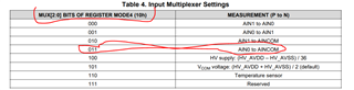
2) Changing the input mux bits of register(10h) to AIN0 to AINCOM as shown in the attached figure.

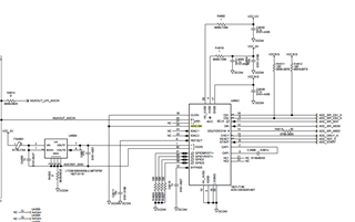
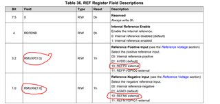
3) External reference is enabled in the design as shown in the attached figure.


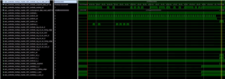
I have set the PGA gain as 0.125 and given the 5.00v as an input to the ADC.I am getting the x"ecxxxx" hexadecimal value as the ADC conversion output .

I had attached the screenshot of our schematic and waveform from the vivado ila. 

  • Hi Ramesh,

    Have you performed a RREG to confirm that the WREG commands have taken effect? If they have not, for whatever reason, you might get invalid data as a result.

    Just to confirm: is this the data byte you received from the ADC? Do you have the STATUS0 byte enabled (which would be "1E" in the image below)? It is hard to tell because the data CRC does not match in either case.

    If STATUS0 byte is enabled, command structure on DOUT assuming the command given was 12 00 AA:

    • FF = Byte 1 = correct
    • 12 = echo byte = correct
    • 00 = echo byte 2 = correct
    • AA = out CRC-2 = correct (for 12 00)
    • 1E = STATUS0 byte = registers unlocked, no CRC1 error, errors in STATUS1 or STATUS 2, REF alarm, new data are ready, clock is external
    • EC = Data MSB
    • 93  = Data mid
    • EB = Data LSB
    • FF = data CRC-4 = incorrect (CRC-4 should be 07 for 1E EC 93 EB)

    If STATUS0 byte is disabled, command structure on DOUT assuming the command given was 12 00 AA:

    • FF = Byte 1 = correct
    • 12 = echo byte = correct
    • 00 = echo byte 2 = correct
    • AA = out CRC-2 = correct (for 12 00)
    • 1E = Data MSB
    • EC  = Data mid
    • 93 = Data LSB
    • EA = data CRC-3 = incorrect (CRC-4 should be EB for 1E EC 93)

    So it seems in either case the CRC is incorrect unless I am missing something. This means there is some communication error between the ADC and MCU. You might check for noise or anything else that can interfere with the digital communication lines.

    Please let me know what you try and the outcomes of your tests.

    -Bryan