This thread has been locked.

If you have a related question, please click the "Ask a related question" button in the top right corner. The newly created question will be automatically linked to this question.

ADS54J42: Error Vector Magnitude(EVM) deviation on the ADS54J42

Part Number: ADS54J42
Other Parts Discussed in Thread: ADS54J40

Hello,

My customer tested the error vector magnitude(EVM) of a 5G NR signal with the following configuration.

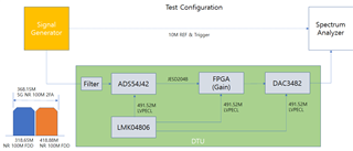
The result of measuring EVM while changing the SG's 5G NR signal power to -24dBm and -4dBm two cases is as follows.

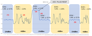
  (1) It shows stable EVM characteristics for -24dBm input.

  (2) When changing to -4dBm, the EVM deviation increases to about 1% and is unstable.

  (3) If you change the input to -24dBm when the EVM value is bad, the EVM deviation will be stabilized, but the EVM value will remain bad.

  (4) Running a PULSE RESET of the ADS54J42 makes the EVM values good again.

  (5) If changing the input from -4dBm input to -24dBm at the moment when EVM value is good, both EVM deviation and EVM value are normal.

Please advise on the causes and solutions of the above abnormal symptoms.

Thanks a lot.

JH

  • JH,

    What is the center frequency of the NR signal, the PAR ( peak to average ratio), decimation mode (if used) and the sample rate used by the ADC?

     Regards,

    Jim

  • Hello Jim,

    Thanks for your help.

    The center frequency and PAR of the NR signal is 318.65MHz and 10dB.

    The ADC sample rate is 491.52MHz and decimation mode is not used.

    Regards,

    JH

  • JH,

    Can you try backing off to -8dbm avg for NR to check that the ADC is not saturated at the peak issue?

    Is it possible to get time domain code data?

    Regards,

    Jim

  • Hi Jim,

    Below is additional information confirmed by the customer via test.

      1. ADC overfloor level : +12dBm @ CW or -1dBm @ NR 2FA

      2. Poor evm deviation : -14dBm @ NR 2FA or more

      3. Stable evm deviation : -15dBm  @ NR 2FA or less

    Please refer to the following ADC dump files.

    ADCDump_20210909.zip

    Regards,

    JH

  • Hi Jim,

    The customer found that the evm is stable when turning off IL mismatch compensation described only in the ADS54J40 datasheet. However, the evm value is worse than when this function is turned on.

    Would it be okay to apply the contents of IL mismatch compensation described in the ADS54J40 datasheet to the ADS54J42 in the same way?

    If there is a procedure to optimize the IL mismatch compensation function for the ADS54J42, please provide it.

    Regards,

    JH

  • JH,

    Please provide the customer with the attached document. The ADS54J40 data sheet has the most up-to-date information in this family of parts and the info will apply to the ADS54J42 as well.

    Regards,

    Jim

    8765.ADS54J60_OS_IL_freeze.pptx

  • Jim,

    My customer has some questions about the pptx file.

    1. Please explain in which case each of the two flow cases should be applied.

    2. Even though register 0x4005 is set to 0x0, why do registers 0x6068 and 0x7068 need to be controlled separately from each other? Are the two registers independent of the 0x4005 setting?

    3. Why is DC OFFSET CORR BW set to 5h in register 0x6068 in DC cal flow? I would like to know the selection criteria for that value.

    Thank you.

    JH

  • JH,

    1. The first flow should be done after powerup. The second flow should be done for approximately every 5C change in temperature. During the change of temperature of +/-5C, the spurs will be higher than at  the original temperature. Depending on what level of spur the user can tolerate will determine how often they should repeat the calibration.

    2. These were added in case the customer wants to make changes per channel. There is no issue with either skipping the writes to CHB or doing them as shown per the document. 

     3. This is the best BW setting for convergence. 

    Regards,

    Jim