This thread has been locked.

If you have a related question, please click the "Ask a related question" button in the top right corner. The newly created question will be automatically linked to this question.

DAC161P997: DAC Refresh Rate and connecting/disconnecting output circuit

Part Number: DAC161P997
Other Parts Discussed in Thread: DAC161S997

Hi,

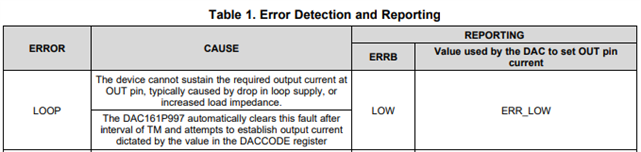
We are running into a behavior with the dac161p997 that does not appear to be documented in the datasheet. 

1. The DAC has been configured to mask LOOP and CHANNEL errors.
2. If we have a multimeter connected to the DAC output circuit during power up, and update the DAC output every 1000 ms (1 sec), everything works as expected as long as the multimeter is connected. However, if we disconnect the multimeter, and then reconnect it, the current output is stuck at the ERR_LOW value (around 3.37 mA). Same is true if we disconnect the multimeter during power up, and reconnect it later - the output is stuck at the ERR_LOW value. 
3. If however we refresh the DAC at 50 ms intervals, we can connect and disconnect the multimeter as we please, the the current output shows the expected value. 

We would like to know why we have to refresh the DAC at these faster intervals, especially when the CHANNEL error has been masked, and if there is any documentation that supports this observed behavior.

Thanks,

Muhammad A. Rahim


  • Muhammad,


    First, this does seem like this is some sort of SPI timeout (or channel error). The DAC161S997 expects to receive periodic write commands to ensure that the SPI is continuously working. This would certainly explain why the error goes away when the periodic update occurs at 50ms. However, it seems strange that the loop works only when the multimeter is connected. Are you measuring the current using the multimeter as an ammeter or are you measuring the a voltage across a loop receiver resistor? With the ERR_LOW value, it does seem that the device is sensing an error and reacting to it.

    First, I was hoping that you could post a schematic, or a basic schematic of how it is connected. With the multimeter affecting the operation of the device, I just wanted to see how the device was connected and how the multimeter might be affecting it.

    Second, at the end of the post, you mentioned that the device works when the DAC is refreshed at faster intervals, especially when the channel error is masked. Is the last part of the comment correct in that when the channel error is masked, the loop works and the current output is as expected? This would also indicate that this is a channel error.

    Again, the multimeter affecting operation seems a bit strange. However, with the device being sensitive to the DAC refresh at 50ms intervals, it does seem like the device is giving the channel error (even with it being masked). This is supported by the fact that device appears to be giving the ERR_LOW current. Read the status register to see if the device is giving the SPI_TIMEOUT_ERR (or any other error) and check to see that ERRB is low. If the SPI_TIMEOUT_ERR is set, then I'd go back and make sure that the MASK_SPI_TOUT bit is set to 1. 


    Joseph Wu

  • Muhammad,


    I just realized that your question was for the DAC161P997 and I'd written the response for the DAC161S997. I would note that the DAC161P997 does not have the status register that you can read, but it does have a similar SWIF timeout period of 100ms given as TM in the datasheet.

    In this case, I would make sure the write to CONFIG2 does set the CHANNEL bit to 0 disable the channel-inactive reporting. Because you don't have a specific status register to read, this makes the debugging a bit more difficult. You may be able to check different errors individually by enabling the reporting in CONFIG2 for the different functions. I would check the ACKB for the communication, and enable the reporting one at a time.


    Joseph Wu

  • Hi Joseph,

    Thanks for your response. Couple of things I wanted to mention:

    1. We did tests with both the CHANNEL error masked and enabled. With it enabled, we NEVER get current output value (when we are refreshing at 1000 ms intervals instead of 50 ms) and are perpetually stuck in the ERR_LOW value. With it masked, everything seems operational as long as the multimeter is connected, but as soon as we disconnect it, we are stuck at the ERR_LOW value. So it appears that masking the channel error is having some effect. It just seems seems that not refreshing the DAC output at fast intervals is causing the LOOP error not to reset itself.

    2. We are using the multimeter as an ammeter. 

    Thanks,

    Muhammad

  • Hi Muhammad,

    Joe is out of office today, but short reply on monday.

    Thanks,

    Paul

  • Muhammad,

    I'm sorry I lost track of this thread and forgot to respond on Monday.

    If the communication interval is 1000ms, and if the channel error is enabled, then you would definitely never get the proper current output value and it should read the ERR_LOW value. However with the channel error masked, the device shouldn't be in error, and you would normally get the correct output. With the lack of a multimeter connection, you shouldn't get some effect that causes the channel error. However, you could have some sort of LOOP error. If there is a LOOP error you still may get the ERR_LOW current. If the ammeter is removed, this error may be a LOOP error and not a CHANNEL error.

    Because the multimeter is being used as an ammeter, it may be affecting the loop in some way. How do you have it connected to your circuit? In my previous post, I did ask for a schematic, and I was hoping to see what it looks like.

    Just as a reminder from Table 1, the LOOP error can be caused by the following:

    Joseph Wu

  • Joseph,

    Richard here.  I am an Electronics Engineer that works with Muhammad.  We are using an ammeter to measure the output current.  From what you have shown, opening the loop should create a loop error as the load goes to infinity.  Still the error should be cleared within TM of reconnecting the ammeter.  Could there be an issue because of the ammeter's low shunt resistance?

    Sending a schematic is a bit problematic because this is an open forum and because of ITAR.  I will see if we could send a fragment.  Is there any way we could send it privately over a secure connection?

  • Richard,

    I've sent a friend request on E2E (and sent a friend request with Muhammad as well). Once you've accepted, you can set a direct note to me using the messaging at the upper right hand corner of the E2E window. That way you can send a schematic, and we can discuss specific details away from the forum.

    Joseph Wu

  • Just to recap the test results:

    Test Case #1:
    Loop Error Masked / Enabled
    Channel Error Masked
    Refresh Rate: 1000 ms
    Action: Multimeter always connected (from power up)
    Result: Current Output working

    Test Case #2:
    Loop Error Masked / Enabled
    Channel Error Masked
    Refresh Rate: 1000 ms
    Action: Disconnect Multimeter prior to startup, and reconnect after power up 
    Result: Current stuck at the under-range value

    Test Case #3:
    Loop Error Masked / Enabled
    Channel Error Masked
    Refresh Rate: 1000 ms
    Action: Disconnect Multimeter after power up, and reconnect later
    Result: Current output working until disconnect, after which it is always stuck at under-range value

    Test Case #4:
    Loop Error Masked / Enabled
    Channel Error Enabled
    Refresh Rate: 1000 ms
    Action: Does not matter
    Result: Current Output always stuck at the under-range value

    Test Case #5:
    Loop Error Masked / Enabled
    Channel Error Masked
    Refresh Rate: 50 ms
    Action: Disconnect multimeter prior to power up and reconnect later
    Result: Current Output working

    Test Case #6:
    Loop Error Masked / Enabled
    Channel Error Masked
    Refresh Rate: 50 ms
    Action: Disconnect Multimeter after power up, and reconnect again
    Result: Current Output working

    Summary:
    Enabling / masking the loop error does not seem to matter
    Enabling / masking the channel error does matter - refresh rate needs to be less than 50 ms for it to work at all. This matches the datasheet specs
    Output current seems to work fine if we connect / disconnect multimeter, AS LONG AS refresh rate is 50 ms. If the refresh rate is 1000 ms, the output current only works if the multimeter is always connected to the circuit (from power up)

  • Muhammad,

    Thanks for the test details. I'll look through this to see if there's anything else that we didn't cover in the call.

    Joseph Wu

  • We did the extra tests that you requested:

    1. Set the ERR_LVL to 1 instead of 0. 

    This resulted in the output DAC value to show over-range value now: 21.xx mA. This confirms your suspicion that the CHANNEL error is somehow coming back


    2. Re-configured the registers periodically (10 second intervals). 

    This resulted in the DAC to become functional again (showing the correct output current). So again, your suspicion that the register was somehow getting overwritten (maybe due to a reset) and the CHANNEL error was getting re-enabled when we disconnected the multimeter and reconnected it appears to be correct. However, we cannot tell if this is because the DAC is getting reset (the multimeter never showed the underrange value when we disconnected and then reconnected, but that could be because it is not fast enough).

  • Muhammad,


    Based on your test, it looks the channel error mask is being repeatedly disabled after being enabled. You could check the communication just to see if there is any sort of reset being sent to the device, but my guess is that there is something happening with the supply. If the supply is briefly brought low, then the device may be going through a power-on reset. This would reset the device back to the original state, reinstating the channel error. With ERRLVL=1, this distinguishes the device from the LOOP error. Because more communication with device, shorter than the TM (timeout period) gives you no problems, it seems that the error is not a PARITY or FRAME error. 

    I'm not sure how to best track down this error. My first thought would be to check that the power supply doesn't have any strange transient pulses that might take the supply low. I would also check to see that there aren't a lot of inductances in the supply/ground lines. Any inductance and fast changes in current would cause problems with the supply from a large dI/dt (voltage spikes for example). 

    Another thing to try would be to see if you can connect another external power supply to make sure that VA and VD are not interrupted.


    Joseph Wu

  • Joseph,

    In case the power supply was glitching, we added 100uF to the 24V supply and to the 3.3V supply and measured the voltages while testing.  It doesn't appear that the supply is glitching as this didn't help.  We changed the firmware so that it would output 7mA in the steady on state.  Connecting and reconnecting, it would go to 20mA before going to 7mA showing that it was resetting.  Resetting it makes it work.  Any suggestions?

  • Richard, 

    If the output is returning to 7mA, then I'm going to guess that this is not the power supply going through some sort of POR problem. 

    Could this be a problem with the communication with the channel error mask? Perhaps the setting of the channel error mask is not being set at all. It could either be that the communication for that is setting the wrong bit, or it is repeatedly sending bad parity when writing the channel error mask? 

    Can you check this communication? I might also look at the SWIF communication with an oscilloscope (fair warning: I haven't seen much SWIF communication, so it may take some time reviewing it).

    Joseph Wu 

  • Joseph,

    Is there any way to tell if the DAC is reset?  Upon power up of whole board, the micro resets the DAC, but it would be good to know if the DAC is being reset independently from the rest of the board. We looked at the supplies and saw no anomalies.  We have demonstrated the fact the Channel Error Mask is working as we see different behavior with it set and not set.  Purposely resetting the DAC works. It is as if the process for recovering from an error gets corrupted.  If we knew that the DAC was reset, we could send a command to reinitialize it.

  • Richard,


    I don't think there's an explicit way to determine that the DAC has been reset. The only thing you can look to is that the DAC output is at some default value instead of the previously programmed value.

    One thing that I wanted to check was to read back the CONFIG2 register. Once the channel error mask is enabled, have you gone back to read that it has been set? Again, I've never used SWIF before, but the communication for the DAC161P997 is half-duplex, and you should be able to get the read back from the register. You could power up the device with the multimeter disconnected, and then read the register to see that the device received the command. After that, you could re-insert the multimeter and then read back the register value again. Really, you could enable all the error masks to see that the device powers back up.


    Joseph Wu

  • Joseph,

    We see no way in the  datasheet to read any of the registers.  Maybe there is something we missed.  Could we set up another meeting to discuss this?  Thursday anytime from 10am to noon or 2pm to 5pm; what would work for you?

  • Richard,

    Sorry, I noticed in the datasheet that the SWIF is described as being able to operate in half-duplex mode. It also says that the DAC161P997, the acknowledge pulse constitutes the reverse data flowing from the device back to the controller. However reading through it more carefully, there's no indication in the datasheet how this is done.

    I will message you and we can discuss this further.

    Joseph Wu