This thread has been locked.

If you have a related question, please click the "Ask a related question" button in the top right corner. The newly created question will be automatically linked to this question.

ADS1209: Voltage at lowpass filter differing from input voltage

Part Number: ADS1209

Hi,

I am using the ADS1209 part as an ADC for the pressure sensor on a brake line in my Formula SAE vehicle at my university. When testing using this part putting a 0-5V signal from a power supply into the part, then taking the bitstream and filtering it back to analog using an RC lowpass filter (150kOhm and 1nF resp.), I am getting (with the exception of fully saturating the input at 5V) almost exactly half of the input voltage measuring the output of my filter using a multimeter and DSO.

Is this behaviour from this chip normal or have I assumed the operation of this part incorrectly and therefore my testing methodology is flawed. I can attach an image of my schematic using this chip and a diagram of the test setup if required to understand my issue better.

Thanks in advance for any input on this issue.

- Jarrod

  • Hi Jarrod,

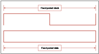
    You can use an RC filter to realize a PWM DAC, but the modulators are not outputting a true PWM signal. Let me try to help you visualize the modulators:


    The modulators work with a fixed clock period and a fixed duty cycle output bit stream of zeros and ones.  The ‘red data’ above, represents one modulator clock period and one data bit.  When operating the ADS1209 for instance at the full scale linear input voltage, 90% of the output data bits are ones and 10% are zeros.  However the output is random, it won’t be 9 ones with 1 zero over and over. 


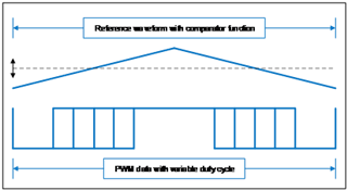
    True PWM data has a variable duty cycle.  The ‘blue data’ above represents a PWM output.  PWM normally has a reference waveform (like a triangle wave) and a comparator function to ‘modulate’ the output data based on an input signal magnitude (i.e. the dashed line) compared to the reference (the triangle wave).  Hopefully that helps – it’s not impossible to use a simple low pass filter with a modulator, but you won’t be able to see much detail in the underlying signal.

    Instead of the RC filter, you could use a sigma-delta filter module, or SDFM to digitally filter the data as explained in the two linked documents below. SDFM's are often integrated into your MCU, such as a C2000, but can also be stand-alone or in an FPGA.

    https://www.ti.com/lit/an/sbaa094/sbaa094.pdf

    https://www.ti.com/lit/an/sbaa230/sbaa230.pdf

  • Hi Alex thanks for your reply.

    As per your suggestion, will using this digital filter give me back an analog voltage back or will the signal that these filters give back be digital still and require further processing after the fact. Also, as per the FSAE ruleset, because this device is being used in a safety system it can't have any programmable logic anywhere in the signal path so will these filters work from factory or is this not possible without programming them?

    Cheers

    - Jarrod

  • Hi Jarrod,

    As far as I know, digital filters are always programmable. Oftentimes, customers use one SDFM for a high resolution, high OSR, high latency measurement for the feedback loop and another SDFM for a low resolution, low OSR, low latency measurement for protection purposes. The digital filter will not give you back an analog voltage but a digital one that can be stored in the MCU and further processed. 

    If you're not too far along in your project, I would suggest taking a look at using discrete amplifiers to accomplish this so that everything can be handled in analog. This cookbook series has a wealth of information in regards to different uses for amplifiers that may help: https://www.ti.com/seclit/eb/slyy137a/slyy137a.pdf