This thread has been locked.

If you have a related question, please click the "Ask a related question" button in the top right corner. The newly created question will be automatically linked to this question.

DAC80502EVM: Unable to set output voltages using MSP430F5152 SPI. Was working before...

Part Number: DAC80502EVM

Hello,

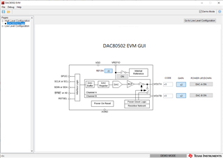
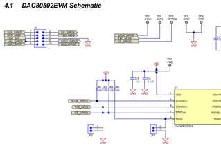
My set-up consists of an MSP-TS430RSB40 Target Socket Module, containing an MSP430F5152, connected to a DAC80502 Evaluation Module via SPI.

During initialization, the code sends a GAIN command to set both channels to a gain of 2: 0x04 0x00 0x03.

I have a function that will send SPI commands to set the DAC-A and DAC-B registers with values calculated based on voltage inputs to a GUI.  For example, trying to set Channel A to 1234mV and Channel B to 2345mV sends the following two SPI messages: 0x08 0x3F 0x2E and 0x09 0x78 0x10.

I used a Saleae on the EM test points and the SPI signals look good.  However, the DAC outputs stay at 0.

Also, this code WAS WORKING before.  I'm wondering if the DAC was accidentally set into a bad state or if there may be some intermittent timing issue...

I appreciate any and all help, thanks!

  • Hi Henry,

    Can you let me you jumper configurations and the EVM supply voltage you are applying. Are you using the internal or external reference?

    One common issue is that the REF-DIV bit is not set in the following cases. If the reference buffer does not have enough headroom then the buffer will shut down and cause the DAC outputs to be 0V. If you supply and reference are right at the edge of one of these cases then that could explain why it worked before. 

    Let me know the above information and we can look into it further.

    Best,

    Katlynne 

  • Hi Katlynne,

    Jumpers 2 and 5 are connected.

    Jumpers 1, 3, and 4 are disconnected.

    We had spent a lot of time debugging it a while ago and discovered the problem was JP2 was disconnected at the time, leaving the DAC in I2C mode.  Once we connected it the DAC was working, but since then it stopped...

    The supply voltage is 5V.

    We don't write anything to the CONFIG register so we should be using the internal reference.

    Thanks for your help!

  • Hi Henry,

    Thanks for the additional details. Can you try increasing the supply or setting the REF-DIV bit to 1 and let me know if the DAC outputs update? The internal reference is 2.5V, so with a 5V supply you are right at the edge of this condition:

    Best,
    Katlynne Jones

  • Hi Katlynne,

    Thank you for the suggestions, I think I'm better understanding the potential headroom issues.

    Unfortunately, I tried increasing the voltage to 5.4V and setting the REF-DIV bit (on separate attempts and together) and the outputs remained 0...

    Thanks,

    Henry

  • Hi Henry,

    When the internal reference is enabled the VREFIO pin is an output. Can you measure the voltage at that pin? You should see 2.5V if the reference is enabled. Try toggling the reference through the CONFIG register and see if you see any change on the pin. If this works then at least we know your SPI is working.

    Another quick check, if you are powering the MSP-TS430RSB40 through JTAG or another supply, is that ground connected to the DAC80502EVM?

    Best,

    Katlynne Jones 

  • Hi Katlynne,

    The VREFIO pin appears to be working.  I measured about 2.5V on TP8.  I then set the REF-PWDWN bit and the VREFIO was about 0V, so the SPI appears to be working as well.

    We are powering both boards with a power supply and the grounds are connected.

    Thanks,

    Henry

  • Hi Henry,

    Can you let me know the exact sequence of commands you were originally sending the device. I've ordered an EVM and I'd like to duplicate your writes. It'll take a few days for me to receive the EVM. 

    If you have a precision multimeter could you also try checking the output and see what state it’s in based on the output of the device with 0x0000 in the DAC-DATA register. The reference should be left on, but here’s the expected output with a couple of different settings:


    DAC-PWDWN=0 (DAC on), REF-DIV=1: VOUT = ~250uV

    DAC-PWDWN=0 (DAC on), REF-DIV=0: VOUT = ~100uV

    DAC-PWDWN=1 (DAC off), REF-DIV=1: VOUT = ~50uV

    DAC-PWDWN=1 (DAC off),REF-DIV=0: VOUT = ~50uV


    It’s very subtle but you may be able to see if the digital settings for the DAC power on and REF-DIV are doing anything.

    Best,

    Katlynne Jones

  • Also, if the DAC output is loaded those values will change. Do you have any load at the output?

  • Hi Katlynne,

    Here are the commands as read from the Saleae:

    0x04 0x00 0x03 - Set the GAINs for both channels to 2.

    0x08 0x3F 0x2E - Write to DAC-A for 1234mV

    0x09 0x78 0x10 - Write to DAC-B for 2345mV

    I'll try checking the outputs...

  • Based on the layout I have, there should be a device connected to the load.  I e-mailed the EEs for details... 

  • Hi Katlynne, I received the following questions from one of the EEs:

    I’m concerned about your statement: “I tried increasing the supply voltage to 5.4V but still was getting 0V.”
    Per the datasheet, this should have worked with REF-DIV bit = 0.
    Can you ask Katlynne for her thoughts on why this may not have worked?
    Also, can you ask her for the logic of an alarm/shutdown state? Would the device be damaged without it?
    Can she recommend an minimum VDD to help ensure we never enter an alarm condition? Is 5.050V sufficient? 5.100V?

  • Hi Henry,

    Was it determined that the reference buffer shutdown was the issue? I suggested increasing the supply as a debug tactic. If you increased the supply and the issue went away, then we would know the reference buffer shutdown was the cause. A supply of 5V will work as long as you don't see a risk of the supply dipping below that in your application. 

    The reference buffer requires sufficient headroom to operate. The buffer is shut down to bring the DAC outputs to a known state (0V) and the alarm condition is to let you know the buffer has been shut down. If you have an I2C controller that you can use, you could try reading the REF-ALARM bit in the STATUS register to confirm if this is the cause of the outputs not updating. 

    Best,

    Katlynne Jones

  • Hi Katlynne,

    We have not been able to determine that the reference buffer shutdown was the issue.

    Is there a way I can add other e-mail addresses to this thread for the notifications?

    Thanks,

    Henry

  • Hi Henry, 

    If the other email addresses are associated with a ti.com account then they can subscribe to the thread. But I am not sure if there is a way to subscribe emails without an account. I will ask my team if any of them know how. Maybe you can set up an auto-forward from the notifications you are receiving.

    Best,

    Katlynne 

  • Hi Henry,

    I asked the e2e team. You can edit your original post and you'll see the option to BCC additional emails, but that'll only send a one time notification. They would then have to set up a ti.com account to subscribe to the thread:

    Best,

    Katlynne 

  • Hey Katlynne,

    When Henry gets the time, I requested he disconnect any switch circuitry from the DAC outputs and retry setting DAC values via SPI with both 5V and 5.4V supplies.

    This eval kit has certainly given Henry a lot of headaches. We're all hoping it's some simple thing we've all overlooked.

    Thanks much for the technical support you've provided to date.

  • Hi Glen,

    Thank you for the update. The EVM I ordered for myself should arrive towards the beginning of next week. I was going to try and recreate Henry's setup, so if there are any other details you can give me about the loads you had at the DAC output that may help. 

    If the device has been damaged, I can also send you another DAC80502EVM so you can continue your evaluation. If we end up seeing similar behavior with the new EVM, this could also help lead us to the root cause. Please let me know if this is something you would be interested in.

    Best,

    Katlynne 

  • Hi Katlynne,

    Glen sent out an e-mail of a couple things to try.  Here it is with my responses, in case it can be of any help...

    JP5 on the DAV eval board determines how the DAC looks at power-up.
    The jumper is currently installed so the DAC powers up to GND (0V).
    If you remove the jumper, the DAC should initialized to midscale (~ 2.5V).
    Henry, you could try removing the jumper to see if the DAC outputs 2.5V after a POR.
    It would give additional confirmation that the DAC outputs are working.

     - I removed the JP5 jumper on the DAC board and read 2.5V on the outputs, as expected.  I put it back on and read 0V.  The output values still weren’t changed when I tried sending SPI messages in either case.

    JP1 jumper on the µP eval board is currently across pins 1 and 2.
    If you have the JTAG connected and the power supply turned on, the jumper should be across pins 2 and 3.
    Henry, do you leave the JTAG connected when you’re developing SW? Do you keep the external P.S. connected? If the answer is yes to both, you should move the JP1 jumper to pins 2 and 3.

    -  I moved JP1 on the µP eval board to pins 2 and 3.  It didn’t make a difference.

    Thanks,
    Henry

  • Hi Henry,

    It is helpful to know that the DAC outputs update to 2.5V when the midscale POR setting is selected through the RSTSEL pin. It is interesting that you are able to toggle the reference output through SPI, and we have verified the outputs are not damaged, but you are still unable to update the DAC outputs. 

    I'd like to send you a new DAC80502EVM and USB2ANY. We can test the current EVM you have with the USB2ANY and GUI provided by TI to see if this makes any difference updating the outputs. We can also test the new DAC80502EVM with your setup and see if the DAC encounters the same update issue. 

    I will send you a private message via e2e.

    Best,

    Katlynne Jones

  • Hi Katlynne,

    Thanks for all your help.  I think the new USB2ANY and DAC EVM will be very helpful.

    I've been using another USB2ANY and I now have an extra DAC EVM, but one or both could be faulty.  For example, the USB2ANY has a blinking light and I've read that indicates there's probably an error.

    Should we try some trouble shooting with this set while we wait for the new ones to arrive?  Is there anything I can do to fix the USB2ANY?

    Thanks again,
    Henry

  • Sure,

    Have you installed the DAC80502EVM GUI software? A few initializations happen when the USB2ANY is plugged into your computer and you run the GUI.

    The blinking is vague so it's hard to know what the problem is. The USB2ANy user's guide says it means "A hardware, firmware, or USB error occurred. Board must be power-cycled.". If you haven't already can you try connecting the USB2ANY to your computer and then running the DAC80502EVM GUI. Make sure the demo mode checkbox is unchecked.

    Best,

    Katlynne 

  • Hi Katlynne,

    Demo Mode is unchecked:

    And it shows that it's connected:

    ETA: It looks like in the schematic we need a jumper on JP1, is that correct?  If so that would be an issue for this board, JP1 is missing...

    Thanks,
    Henry

  • Hi Henry,

    Great that you got the USB2ANY connected. Do you mean you don't have a jumper to apply to JP1? If you have any way to short the two pins then that would also work. If not, then you can apply an external 3.3V signal to VDD and try with that first. 

    Best,

    Katlynne 

  • Hi Katlynne.

    Thanks for the suggestion.  I applied the 3.3V and it looks like I can communicate to it with the USB2ANY.  I tried the Vref test and was able to turn off and on the reference voltage at the test point using the CONFIG register.

    I tried setting the GAIN, DAC_A, and DAC_B registers and still don't see any voltage on the outputs, though.

    Thanks,

    Henry

  • Hi Henry,

    In this case with the 3.3V VDD you will have to set the ref-div bit to 1. Can you try setting that bit and updating the DAC output?

    Selecting the ref div /2 on the high level GUI page should do it for you. 

    Thanks,

    Katlynne 

  • Hi Katlynne,

    This worked!
    First I set the GAIN register to 0x0103 which should set the REF_DIV and both buffer gains.
    Then I wrote DAC_A to 0xCCCC (2V) and DAC_B to 0x6666 (1V).  I measured both and they were correct.

    Now we need to get up to 5V outputs on the channels.  Is it safe to increase VDD to 5V on the EVM with the USB2ANY connected?

    Thanks,
    Henry

  • Hi Henry,

    You can try raising the external VDD to 5V and un-setting the REF-DIV bit. The 3.3V SPI signals through the USB2ANY should still be able to communicate with the device. 

    Best,

    Katlynne

  • Hi Katlynne,

    Using USB2ANY to set near 5V outputs worked on the solitary DAC EVM board.  I then tried it on our two set-up boards and it worked for one but not the other.  I think for now I'll need to focus on the one that worked...

    I tried using the MSP430 to set the DAC outputs on the board that worked with the USB2ANY, but my software still left it at 0V.  Should I be able to open up the USB2ANY and probe the pins to see the SPI signals coming from it?  Then I could compare them to the ones I'm sending from the MSP430...

    Otherwise, is there another approach I should take next?

    Thanks,

    Henry

  • Hi Henry,

    It looks like test points TP1, TP4, and TP5 would allow you to probe the SPI signals on the EVM:

    If you are trying to look at the signals with the USB2ANY disconnected from the EVM, then you can use those small male to male jumper wires if you have any available and plug them in to the appropriate pins on the USB2ANY ribbon cable. Attach your scope probes to the other end.

    Best,

    Katlynne 

  • Hi Katlynne,

    Thank you, those were the test points I was using for monitoring the signals coming from the processor.  I should have realized they would work the same way for the USB2ANY...

    I'm noticing a couple things:
    1. I put the setting of GAIN in my DAC init function and I'm not seeing the messages go out on the analyzer unless I step through the code.  I wonder if it's just because the processor didn't reset when I power cycle the rest of the board, including the DAC.
    2. My code currently sends SPI messages for both DAC channels one right after the other because I have both tied to one button on the GUI.  I wonder if they're too close together.

    So I'm thinking I'll try changing the code so each DAC output has to be set with individual buttons.
    I also might change the code to send the GAIN message before each DAC message.  But then I'm concerned those messages may be too close together, and I don't want to send the GAIN message more times than I need to...

    What are your thoughts?  Do you think those changes will help?

    Thanks,

    Henry

  • Hi Henry,

    Do you see the DAC outputs update when you step through your code? The time between the DAC data SPI updates shouldn't be an issue as long as you see each SPI frame on your scope, and the timing requirements from the datasheet are being met. 

    The sync high time would represent the minimum time between frames. 

  • Hi Katlynne,

    After doing some more runs and looking at the analyzer data more I think I found the problem.  I had the MSP430 SPI clock polarity set to inactive state is low.  I changed it to inactive state is high and now it appears to be working.  I don't now why it was working before, like for setting the reference voltage, but that appears to have been the problem.

    Thank you very much for all your help!

    Henry

  • Hi Henry,

    The clock polarity can idle high or low as long as the phase is set so that the data is captured on the falling edge. Maybe you were just getting lucky with the timing in those cases and the DAC was still able to interpret the data correctly. I'm very glad that you were able to find the issue!

    Please let me know if I can help you with anything else in the future. 

    Best,

    Katlynne