This thread has been locked.

If you have a related question, please click the "Ask a related question" button in the top right corner. The newly created question will be automatically linked to this question.

DAC7750: Not getting current output at IOUT pin

Part Number: DAC7750

Greetings,

I have interfaced a PIC controller to DAC7750 on SPI bus and given a common power supply(12Vdc) to both circuits. I am able to write and read back all registers like control, configuration, DAC data register etc

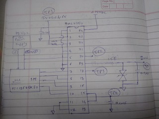
I have checked voltages at DVDD=4.6V, REFIN=REFOUT=5V, R3-SENSE=BOOST=AVDD=12V which are also fine according to datasheet. I have shared a schematic herein, what is wrong in it?.

.
//Following is the initialization code for DAC7750,

//-----------------------------------------------------------------------------------------------------------------------------------------------------

void Init_DAC7750(void)
{
uint16_t data;
char lbuf[100];
//IC reset command.
DAC7750_Write_Register(DAC7750_ADDR_WR_RESET,0x0001);
__delay_ms(100);
//External current setting resistor disable, Output enable, Slew Rate disable, Daisy-chain disable, Output range = 4-20mA.
DAC7750_Write_Register(DAC7750_ADDR_WR_CTRL,0x1005);
__delay_ms(10);
data = DAC7750_Read_Register(DAC7750_READ_CTRL);
sprintf(lbuf,"Control register value=%X\r\n",data);
Tx_String(lbuf);
//calibration enable, HART interface disable, frame error checking disable, Watchdog timer disable
DAC7750_Write_Register(DAC7750_ADDR_WR_CFG,0x0020);
__delay_ms(10);
data = DAC7750_Read_Register(DAC7750_READ_CFG);
sprintf(lbuf,"Configure register value=%X\r\n",data);
Tx_String(lbuf);

DAC7750_Write_Register(DAC7750_ADDR_WR_DAC_GAIN,0x8000);
__delay_ms(10);
data = DAC7750_Read_Register(DAC7750_READ_DAC_GAIN);
sprintf(lbuf,"Gain register value=%X\r\n",data);
Tx_String(lbuf);

DAC7750_Write_Register(DAC7750_ADDR_WR_DAC,0x0000);
__delay_ms(10);
data = DAC7750_Read_Register(DAC7750_READ_DAC_DATA);
sprintf(lbuf,"DAC register value=%X\r\n",data);
Tx_String(lbuf);
}

//---------------------------------------------------------------------------------------------------------------------------------------------------

Out put on terminal is what i expected,

Control register value=1005

Configure register value=0020

Gain register value=8000

DAC register value=0

//-----------------------------------------------------------------------------------------------------------------------------------------------------

That means my code is working fine but when i connect digital multimeter to check for current then there is always 0mA current, even if i load DAC data register with 0xFFF0 value.

Please help me in this.

Best regards,

Santosh.

  • Hi Santosh,

    I forwarded your query to my team Mr. Joe, he will response by end of today.

  • Hello A. Mani,

    Thanks in advance.

  • Santosh,


    I don't see anything wrong with the schematic and it looks like you've verified the supply, DVDD and reference voltages. Just in case you can compare it against the EVM schematic. Also, if you can write and readback from the registers, I would also guess that you have the digital communications connected correctly. Just make sure that the readback is correct.

    If you have the control register set to 0x1005, it means that you have the output enabled and the range set to the 4-20mA range. With the gain calibration range set to 0x8000 and the user calibration enabled in the configuration register set to 0x0020, the device should be giving the expected output code.

    Looking at the registers, I don't see anything that could be wrong.

    Reset register 0x0001 - write reset (I would write back 0x0000, but it shouldn't make a difference) 

    Data register 0x0000 - set to minimum

    Control register 0x1005 - DAC output enabled, range set to 4 -20mA

    Configuration register 0x0020 - User calibration enabled

    Gain coefficient register 0x8000 - Code out equivalent to DAC code

    With these settings, the output should be at the minimum of 4mA. I've tested this out with the EVM and read back the registers for this setting. Using the 300 Ohm load on the board, I can see that the output is basically 1.2V. 

    I'm not sure why your setup isn't setting the output, but I would first check all the circuit connections. What resistive load are you using on your setup? 


    Joseph Wu

  • Dear Joseph,

    Thanks for your reply,

    I have read back all registers and got the correct values as you can see in first query, in that i have sent the readback values on serial terminal.

    I have used 470 Ohm resistor at the output terminal as load. Since i am getting 0Voltage across the resistor, hence the current is always 0V even though I change the value of DAC register.

    Alarm, Boost and HART communication is not implemented, i have connected basic minimal required connections in my schematic.

    Only difference between EVM and mine schematic is external ISET-R register and HART communication implementation, so is that make any impact on output?

    Best regards.

  • Santosh,


    I had thought that you had used the internal resistor. Your diagram doesn't show a resistor (pin 13 was shown as floating - but should have been grounded) Using the ISET-R resistor, you would still need to set DB13 of the control register high. Setting the bit high enables the external current setting resistor. In that case the control register write would be 0x3005.

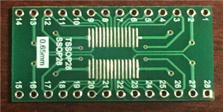
    Can you show me a photo of your setup? One thing that I had see in the past was a soldered down device on a board similar to the one below:

    One of the issues is that the DAC7750 has a thermal pad underneath the device. With longer leads under the device, they made contact with the thermal pad and shorted pins out. Hopefully this isn't a problem for you. With communications working, but the DAC output still low, I would check to make sure that the DAC Clear pin is low. It's one of the other things that might affect the DAC output. Also, I would disable the user calibration. At this point, I would simplify the operation and just use the normal DAC code. 

    Again, I don't see anything wrong in the schematic. For the most part it's similar to the diagram in Figure 62 which is a rather simplified operation. However, if there is a problem in the schematic, it might be easier to use the EVM for evaluating the connections. If you can get the DAC7750EVM, you could still just wire your microcontroller to the digital connections.

    Joseph Wu

  • Hi Joseph,

    Yes you are right i have used internal resistor hence no extrenal resistor is connected(pin is floating). 

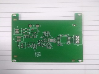
    I have a costum board soldered with minimal componets to test DAC7750 IC and taken out wires from this board externally. 

    Footprint provided for the IC is according to datatsheet so there is no chance of shorted pins. DAC clear pin(CLR) is connected to ground. By disabling the calibration the result was same, no output at Iout pi.

    Now I will try by connecting ISET-R pin to ground and will inform you soon.

    Best regards.

  • Hi Joseph,

    Now I am getting output on Iout pin by giving solder touchup on all components.

    But it's working for some cycles only, mean when i change the value of DAC register from 0 to 4095 in step of 1024 then output change from 4 - 8 - 12 - 16 - 20 for some cycles only. I have inserted 2 Sec delay between each step to monitor current on Multimeter.

    Best regards.

  • Santosh,

    I'm glad that you were able to get something on IOUT. However, you mentioned that you were only able to get the outputs on some of the cycles. Do you think this is a digital error or some other connection problem?

    Joseph Wu

  • Hello Joseph,

    Thank you for your kind cooperations, Now everythink is working fine the problem was is solved by soldering CAP1 and CAP2 capacitors

    Thanks and best regards.