This thread has been locked.

If you have a related question, please click the "Ask a related question" button in the top right corner. The newly created question will be automatically linked to this question.

AFE4900: PTT Mode for TIDA-01580

Part Number: AFE4900
Other Parts Discussed in Thread: TIDA-01580,

Hello,
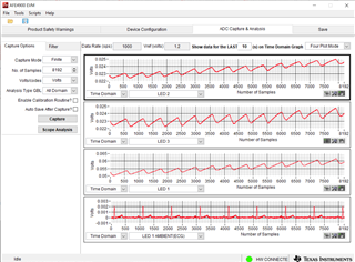
I am using the TIDA-01580 board and want to change it to PTT mode (1khz), however  I am unable to get any data. Can you please tell me the values of each register to use for 1khz PRF for TIDA-01580.

I have tried the following register settings. (Internal 128khz oscillator with division factor of 4)

{0x00, 0x000020}, /*CONTROL0*/
{0x01, 0x00001}, //-// /*LED2STC*/
{0x02, 0x00003}, //-// /*LED2ENDC*/
{0x03, 0x0000A}, //-// /*LED1LEDSTC*/
{0x04, 0x0000D}, //-// /*LED1LEDENDC*/
{0x05, 0x00006}, //-// /*ALED2STC*/
{0x06, 0x00008}, //-// /*ALED2ENDC*/
{0x07, 0x0000B}, //-// /*LED1STC*/
{0x08, 0x0000D}, //-// /*LED1ENDC*/
{0x09, 0x0000}, //-// /*LED2LEDSTC*/
{0x0A, 0x00003}, //-// /*LED2LEDENDC*/
{0x0B, 0x000010}, //-// /*ALED1STC*/
{0x0C, 0x000012}, //-// /*ALED1ENDC*/
{0x0D, 0x00005}, //-// /*LED2CONVST*/
{0x0E, 0x00008}, //-// /*LED2CONVEND*/
{0x0F, 0x0000A}, //-// /*ALED2CONVST*/
{0x10, 0x0000D}, //-// /*ALED2CONVEND*/
{0x11, 0x0000F}, //-// /*LED1CONVST*/
{0x12, 0x000012}, //-// /*LED1CONVEND*/
{0x13, 0x000014}, //-// /*ALED1CONVST*/
{0x14, 0x000017}, //-// /*ALED1CONVEND*/
{0x1D, 0x00001F}, //-// /*PRPCOUNT*/
{0x1E, 0x000101}, /*CONTROL1*/ //TIMER ENABLED AND NUMAV=1
{0x1F, 0x000000}, /*TIAGAIN_2_3*/
{0x20, 0x000003}, /*TIAGAIN*/
{0x21, 0x000003}, /*TIA_AMB_GAIN*/
{0x22, 0xFC0000}, /*LEDCNTRL1*/ //LED CURRENT CONTROL REGISTER
{0x23, 0x104218}, /*CONTROL2*/ //OSCILLATOR SELECT AND ILED_FS
{0x24, 0x000600}, /*LEDCNTRL2*/
{0x28, 0x000000}, /*TOGGLE*/
{0x29, 0x000000}, /*CLKDIV1*/
{0x2A, 0x000000}, /*LED2VAL*/
{0x2B, 0x000000}, /*ALED2VAL*/
{0x2C, 0x000000}, /*LED1VAL*/
{0x2D, 0x000000}, /*ALED1VAL*/
{0x2E, 0x000000}, /*LED2-ALED2VAL*/
{0x2F, 0x000000}, /*LED1-ALED1VAL*/
{0x31, 0x000020}, /*CONTROL3*/
{0x34, 0x000000}, /*PROG_INT2_STC*/
{0x35, 0x000000}, /*PROG_INT2_ENDC*/
{0x36, 0x00005}, //-// /*LED3LEDSTC*/
{0x37, 0x00008}, //-// /*LED3LEDENDC*/
{0x39, 0x000005}, /*CLKDIV2*/ //CLOCK DIVISION 128K/4=32K
{0x3A, 0x100000}, /*OFFDAC*/
{0x3B, 0x000000}, /*THRDETLOW*/
{0x3C, 0x000000}, /*THRDETHIGH*/
{0x3D, 0x000000}, /*THRDET*/
{0x3E, 0x000000}, /*I_OFFDAC*/
{0x3F, 0x000000}, /*AVG_LED2_ALED2VAL*/
{0x40, 0x000000}, /*AVG_LED1_ALED1VAL*/
{0x42, 0x000000}, /*FIFO*/
{0x43, 0x0000F}, //-// /*LED4LEDSTC*/
{0x44, 0x000012}, //-// /*LED4LEDENDC*/
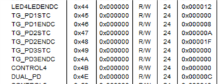
{0x45, 0x000000}, /*TG_PD1STC*/
{0x46, 0x000000}, /*TG_PD1ENDC*/
{0x47, 0x000000}, /*TG_PD2STC*/
{0x48, 0x000000}, /*TG_PD2ENDC*/
{0x49, 0x000000}, /*TG_PD3STC*/
{0x4A, 0x000000}, /*TG_PD3ENDC*/
{0x4B, 0x000000}, /*CONTROL4*/ /////////DOUBT///////
{0x4E, 0x000004}, /*DUAL_PD*/ //PTT MODE
{0x50, 0x000018}, /*CONTROL5*/ ///SHORT_ALDO_TO_DLDO_IN_DEEP_SLEEP - 0///
{0x51, 0x000000}, /*FIFO_OFFSET*/
{0x52, 0x00001D}, //-// /*DATA_RDY_STC*/
{0x53, 0x00001D}, //-// /*DATA_RDY_ENDC*/
{0x54, 0x000000}, /*MASK_PPG*/
{0x57, 0x000000}, /*PROG_INT1_STC*/
{0x58, 0x000000}, /*PROG_INT1_ENDC*/
{0x61, 0x080000}, /*ECG_CHOP*/
{0x62, 0x800000}, /*ECG_RLD*/
{0x63, 0x000000}, /*RCOMP*/
{0x64, 0x000000}, //-// /*DYN_TIA_STC*/
{0x65, 0x000020}, //-// /*DYN_TIA_ENDC*/
{0x66, 0x000000}, //-// /*DYN_ADC_STC*/
{0x67, 0x000020}, //-// /*DYN_ADC_ENDC*/
{0x68, 0x000000}, //-// /*DYN_CLOCK_STC*/
{0x69, 0x000020}, //-// /*DYN_CLOCK_ENDC*/
{0x6A, 0x000021}, //-// /*DEEP_SLEEP_STC*/
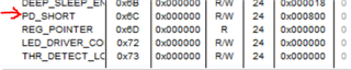
{0x6B, 0x000018}, //-// /*DEEP_SLEEP_ENDC*/
{0x6C, 0x000000}, /*PD_SHORT*/
{0x6D, 0x000000}, /*REG_POINTER*/
{0x72, 0x000000}, /*LED_DRIVER_CONTROL*/
{0x73, 0x000000}, /*THR_DETECT_LOGIC*/

{0xFF, 0x00} //End of Array

  • Hello Malik

    I noticed an issue in the register settings. It seems like you have not enabled the dual PD mode and the respective TG PD settings.  TIDA-01580 reference design uses SFH 7072 sensor. For more optimal readings, the Green LED of the sensor should be used with the IR cut PD and the red and IR LEDs be used with broadband PD. You can use the AFE4900 GUI for the register settings needed to program. With these register settings updated, I am able to use the AFE4900 EVM and capture the PPG signals and ECG signals (for ECG I used a simulator).

  • Thank you. I have made the changed accordingly but Im still not getting any data from AFE. The current register settings are:

    AFE4900_Reg_Write(0, 0x20); //ENABLE ULP mode
    AFE4900_Reg_Write(1, 0x1); //AFE_LED2STC
    AFE4900_Reg_Write(2, 0x3); //AFE_LED2ENDC
    AFE4900_Reg_Write(3, 0xA); //AFE_LED1LEDSTC
    AFE4900_Reg_Write(4, 0xD); //AFE_LED1LEDENDC
    AFE4900_Reg_Write(5, 0x6); //AFE_ALED2STC
    AFE4900_Reg_Write(6, 0x8); //AFE_ALED2ENDC
    AFE4900_Reg_Write(7, 0xB); //AFE_LED1STC
    AFE4900_Reg_Write(8, 0xD); //AFE_LED1ENDC
    AFE4900_Reg_Write(9, 0x0); //AFE_LED2LEDSTC
    AFE4900_Reg_Write(10,0x3); //AFE_LED2LEDENDC
    AFE4900_Reg_Write(11,0x10); //AFE_ALED1STC
    AFE4900_Reg_Write(12,0x12); //AFE_ALED1ENDC
    AFE4900_Reg_Write(13,0x5); //AFE_LED2CONVST
    AFE4900_Reg_Write(14,0x8); //AFE_LED2CONVEND
    AFE4900_Reg_Write(15,0xA); //AFE_ALED2CONVST
    AFE4900_Reg_Write(16,0xD); //AFE_ALED2CONVEND
    AFE4900_Reg_Write(17,0xF); //AFE_LED1CONVST
    AFE4900_Reg_Write(18,0x12); //AFE_LED1CONVEND
    AFE4900_Reg_Write(19,0x14); //AFE_ALED1CONVST
    AFE4900_Reg_Write(20,0x17); //AFE_ALED1CONVEND

    AFE4900_Reg_Write(29, 0X1F); //AFE_PRPCOUNT // 50Hz PRP @ 128KHz Int OSC CLK

    AFE4900_Reg_Write(30, 0x000101); //AFE_CONTROL1 TimerEN = 1; NUMAV = 0

    AFE4900_Reg_Write(31, 0x000000); //.//

    AFE4900_Reg_Write(32, 0x000003); //AFE_TIA_SEP_GAIN (LED2) ENSEPGAIN = 0; LED2/LED3 gain = 25K
    AFE4900_Reg_Write(33, 0x000003); //AFE_TIA_GAIN (LED1) LED1/LED1AMB gain = 25K

    AFE4900_Reg_Write(34, 0xFC0000); //changed
    AFE4900_Reg_Write(35, 0x104218); //changed

    AFE4900_Reg_Write(36, 0x000600); //.//
    AFE4900_Reg_Write(40, 0x0); //.//
    AFE4900_Reg_Write(41, 0x0); //.//
    AFE4900_Reg_Write(42, 0x0); //.//
    AFE4900_Reg_Write(43, 0x0); //.//
    AFE4900_Reg_Write(44, 0x0); //.//
    AFE4900_Reg_Write(45, 0x0); //.//
    AFE4900_Reg_Write(46, 0x0); //.//
    AFE4900_Reg_Write(47, 0x0); //.//

    AFE4900_Reg_Write(49, 0x20); //ENABLE_INPUT_SHORT = 1
    AFE4900_Reg_Write(50, 0); //PDNCYCLESTC
    AFE4900_Reg_Write(51, 0); //PDNCYCLEENDC
    AFE4900_Reg_Write(52, 0x0); //.//
    AFE4900_Reg_Write(53, 0x0); //.//

    AFE4900_Reg_Write(54, 0x00005); //AFE_LED3LEDSTC
    AFE4900_Reg_Write(55, 0x00008); //AFE_LED3LEDENDC

    AFE4900_Reg_Write(57, 0x000005); //CLKDIV_PRF

    AFE4900_Reg_Write(58, 0x100000); //.//
    AFE4900_Reg_Write(59, 0x0); //.//
    AFE4900_Reg_Write(60, 0x0); //.//
    AFE4900_Reg_Write(61, 0x0); //.//
    AFE4900_Reg_Write(62, 0x0); //.//
    AFE4900_Reg_Write(63, 0x0); //.//
    AFE4900_Reg_Write(64, 0x0); //.//
    AFE4900_Reg_Write(66, 0x0); //.//

    AFE4900_Reg_Write(67, 0x0000F); //AFE_LED4LEDSTC
    AFE4900_Reg_Write(68, 0x000012); //AFE_LED4LEDENDC


    AFE4900_Reg_Write(69, 0x0); //.//
    AFE4900_Reg_Write(70, 0x8); //.//
    AFE4900_Reg_Write(71, 0x0A); //.//
    AFE4900_Reg_Write(72, 0x1F); //.//
    AFE4900_Reg_Write(73, 0x0); //.//
    AFE4900_Reg_Write(74, 0x0); //.//


    AFE4900_Reg_Write(75, 0x00); //CONTROL_DYN_VCM / CONTROL_DYN_DLDO / CONTROL_DYN_ALDO / CONTROL_DYN_BG

    AFE4900_Reg_Write(78, 0x00000C); //DUAL PD

    AFE4900_Reg_Write(80, 0x18); //.//
    AFE4900_Reg_Write(81, 0x0); //.//

    AFE4900_Reg_Write(82, 0x1D); //DATA_RDY_STC
    AFE4900_Reg_Write(83, 0x1D); //DATA_RDY_ENDC

    AFE4900_Reg_Write(84, 0x0); //.//
    AFE4900_Reg_Write(87, 0x0); //.//
    AFE4900_Reg_Write(88, 0x0); //.//

    AFE4900_Reg_Write(97, 0x080000); //ECG CHOP
    AFE4900_Reg_Write(98, 0x800000); //ECG RLD

    AFE4900_Reg_Write(99, 0x0); //.//

    AFE4900_Reg_Write(100, 0); //DYN_TIA_STC
    AFE4900_Reg_Write(101, 0x20); //DYN_TIA_ENDC
    AFE4900_Reg_Write(102, 0); //DYN_ADC_STC
    AFE4900_Reg_Write(103, 0x20); //DYN_ADC_ENDC
    AFE4900_Reg_Write(104, 0); //DYN_CLOCK_STC
    AFE4900_Reg_Write(105, 0x20); //DYN_CLOCK_ENDC
    AFE4900_Reg_Write(106, 0x21); //DEEP_SLEEP_STC
    AFE4900_Reg_Write(107, 0x18); //DEEP_SLEEP_ENDC

    AFE4900_Reg_Write(108, 0x000800); //.//

    AFE4900_Reg_Write(109, 0x0); //.//
    AFE4900_Reg_Write(114, 0x0); //.//
    AFE4900_Reg_Write(115, 0x0); //.//

  • Hi Malik,

    Can you elaborate on what you mean by not getting any data from AFE. Are you unable to read back values programmed in any registers or just the ADC output registers (0x2A through 0x2F)? If it is just the ADC output registers, what values do you read from these registers?

  • After reading back the register values, I get 0 in most of the registers. I set the value of 0th register to 21 before reading the registers. Serial output is listed below
    address: 0 0
    address: 1 1
    address: 2 3
    address: 3 a
    address: 4 d
    address: 5 0
    address: 6 0
    address: 7 0
    address: 8 0
    address: 9 0
    address: 10 0
    address: 11 0
    address: 12 0
    address: 13 0
    address: 14 0
    address: 15 0
    address: 16 0
    address: 17 0
    address: 18 0
    address: 19 0
    address: 20 0
    address: 21 0
    address: 22 0
    address: 23 0
    address: 24 0
    address: 25 0
    address: 26 0
    address: 27 0
    address: 28 0
    address: 29 0
    address: 30 0
    address: 31 0
    address: 32 0
    address: 33 0
    address: 34 0
    address: 35 0
    address: 36 0
    address: 37 0
    address: 38 0

  • Malik,
    Based on the serial output, are you reading back from register address 0? Register 0 is a write only register. So any access to it will clear the SPI_REG_READ bit.