This thread has been locked.

If you have a related question, please click the "Ask a related question" button in the top right corner. The newly created question will be automatically linked to this question.

ADS1262: Is it possible to use ADS1262 to design a 3-wire RTD circuit

Part Number: ADS1262
Other Parts Discussed in Thread: REF7025

Hi Team,

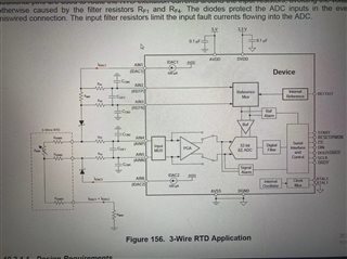
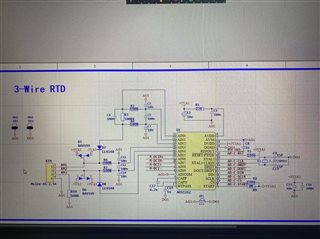
I designed a set of circuit by referring to the three-line RTD circuit in THE data sheet of ADS1262. I want to use ADS1262 channel AIN0-AIN5 to measure RTD, and the remaining channel AIN6-9 to measure two groups of differential signals, which need 2.5V as a reference. The circuit in the figure should take the voltage on the Rref as the external Reference input, which is inconsistent with my requirements. I would like to ask, according to the block diagram, can I configure the Reference Mux to use the internal Reference (2.5V) as the chip Reference voltage, and use the two sets of voltage values of the three-line resistor as measured values? The two sets of differential signals require an accuracy of 0.02%.


Beat Regards,
Tom Liu

  • Hi Tom,

    I am not entirely sure I understand this question - are you just asking if the schematic you have drawn is valid?

    The RTD circuit looks to be setup correctly: you are using a high-side, 3-wire, 2x IDAC configuration, where AIN0 and AIN5 are IDACs, AIN1 and AIN2 are the ratiometric reference inputs, and AIN3 and AIN4 are the measurement channels for the RTD. You do need to switch AIN1 and AIN2, as the trace containing R2 is the positive reference input (REFP) and the trace containing R4 is the negative reference input (REFN). However, AIN1 can only be used as REFN, and AIN2 can only be used as REFP, so you just need to swap these connections on your schematic (see section 9.6.12 for more info). You might also have to adjust the value of RBIAS (R10) to make sure the input voltages are within the ADC's common-mode range, assuming you will enable the PGA.

    I will also point out that the reference resistor (R3) is likely too small for most RTD measurements, but this depends on the type of RTD you intend to measure (PT100, PT1000, etc.) and the temperature range you need to measure. You can learn more about RTD measurements with our helpful guide: https://www.ti.com/lit/an/sbaa275/sbaa275.pdf

    The other two measurements should be fine, assuming they meet the ADC absolute input range requirements. For these measurements it sounds like you will use the ADC's internal reference, which can be enabled via the REFMUX register. Keep in mind that the internal VREF initial accuracy is already 0.1% (0.2% max), which is larger than your error budget. You will either need to calibrate the signal chain, or use a better reference. You can check out the REF7025 for an ultra high performance 2.5V reference.

    -Bryan