Hi Team,
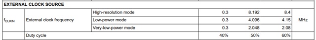
I would like to know a suitable EXTERNAL CLOCK SOURCE.
(I need around 16bit resolution and data rate is TBD.)
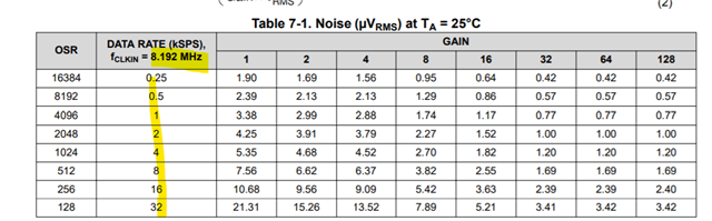
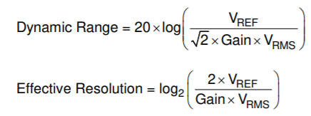
I can find “Table 7-2. Dynamic Range (Effective Resolution) at TA = 25°C” in the datasheet.
Could you please let us know similar table at fCLKIN=4.096 MHz and 2.048 MHz if you have any information?
Regards,
Hide