This thread has been locked.

If you have a related question, please click the "Ask a related question" button in the top right corner. The newly created question will be automatically linked to this question.

ADS8320: The SNR issue

Part Number: ADS8320
Other Parts Discussed in Thread: REF3025, PSIEVM, LMP7716, OPA354

Hi, All:

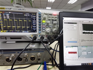
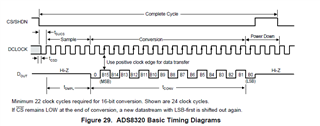
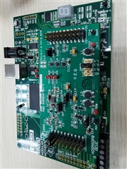
We are planning to use ADS8320 in our project, and we bought an ADS8320EVM and are evaluating the baisc features.

Now we met an issue of SNR.

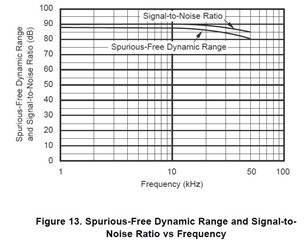
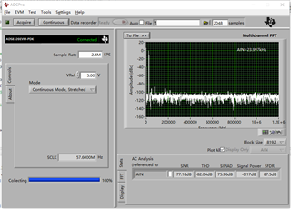
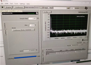
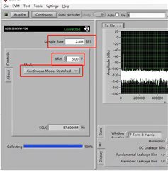
We tested your EVM, the SNR is only about 80dB. it's lower than your specficication (90dB).

our test enviroment:  Vin =5V; input signal:  Sin wave: frequency: 1.021Khz ; Vpp=4.9V; Offest: 2.45V

We also try to adjust the input filter, but the efffect is limited.

Would you give some advices, how to improve the SNR ?  Or which care items we must follow when we evaluated it.

Best Regards

Torres

  • Hello Torres,

    Thank you for your post and for your interest in our ADS8320!

    What is the signal source used to provide the sine wave input? Of course, the SNR of the source must be better than 90 dB in order to see the full ADC performance. Ensure that the ground of the signal source is also well connected to the EVM ground as well, preferably near the analog side of the EVM.

    Are you using an FFT to compute SNR? Do you see other tones in the frequency spectrum, or is the noise fairly Gaussian?

    Regards,

    Ryan

  • Hello Ryan:

    Thanks for your response.

    We used AP515 (From Audio Precision) as signal generator. We also try their APX555, they are both excellent signal generators.

    Today, We tested it again, the best SNR is up to 85dB. it's still lower than 90dB.

    we used your evaluating platform(MMB0 + ADS8320EVM), the frequency spectrum as attached file.

     if possible, Could you verify it in your Lab,. SNR is very important for us, We must know how to improve it.

    Regards

    Torres

  • Hello Torres,

    I would agree that both Audio Precision are excellent signal sources, especially in the ~1kHz frequency range. However, this image shows the input signal is close to 20 kHz, is that correct? We do expect a slight drop-off in SNR performance as the input frequency increases to 20 kHz:

    Regards,

    Ryan

  • Hi, Ryan:

    Actually the input signal is 1.021Khz sin wave. but your GUI displays about 24Khz, it's your GUI problem ,just  like the sample rate, we input 100K, but it displays 2.4M SPS. maybe you can try your EVM if you don't understand it.

    85dB is the best resut we achieved, we tested it many times, 80dB is a typical resut we got.

    Is it possilbe to verify it in your lab? if you can get about 90dB SNR, we want to your test method.

    Regards

    Torres

  • Hi Torres, 

    I did not have an EVM immediately available, so I've ordered a new one for myself to test on the bench. I hope to have results sometime next week.

    In the meantime, something certainly appears to be wrong with the EVM software. The ADS8320 does not even support 2.4 MSPS sampling rates (max is 100 kSPS). Also, the max DCLOCK frequency is 2.4 MHz. I'm surprised the device works at all if the clock is truly 57.6 MHz. Could you try to capture the DCLOCK input on a scope and verify the frequency?

    If I think of any other debug steps in the meantime, I will reply back on here. Otherwise, let me play around with the software myself once the new board arrives.

    Regards,

    Ryan

  • Hi, Ryan:

    Thanks for your information, hope to get your test result next week.

    I explaned the GUI displays issue again, We know the max sample rate is 100kSPS for ADS8320. when we input 100K, the GUI transfer it to 2.4M SPS automatically. when we use 1.021K sin wave, the AIN is about 24Khz .

    I will test the Dclock signal and update it to you, today is weekend.

    Regards

    Torres

  • Hi, Ryan:

    The Dclock is 2.4Mhz, please refer to the below picture.we tested it today.

    Regards

    Torres

  • Hi Torres, 

    Thank you for the update. This is what I was hoping to confirm by your measurements: the GUI display says DCLOCK is 57.6 MHz, but the actual clock that you measured is 2.4 MHz. So functionally, the hardware is doing what we expect. Only the GUI display is incorrect.

    I imagine that the ADC sampling rate is also not 2.4 MSPS, but rather 100 kSPS. You can also confirm this by checking the period of the signal on pin 5 (CSn/SHDN). Falling edge to falling edge is the data rate period.

    Back to the original issue - I still do not have hardware to test. Expected arrival date is this Friday but I'm hopeful it comes sooner. In the meantime, have you tried other capture modes? It looks like the "Continuous, Stretched SCLK Mode" calculates SCLK based on the desired data rate such that it uses the minimum SCLK frequency necessary. Slowing down/slewing clock signals is one way to try and improve SNR.

    What are the jumper positions used during your testing?

    Regards,

    Ryan

  • Hi, Ryan:

    Hope you can get the EVM as soon as possilbe.We are wating for your testing result.

    if your testing resulit is good, we want to know your test method, this is our target.

    we tested the Cs pin / Dclock for the data rate, the resulit is correct and meet the specificaton, we checked the timing diagram many times.

    The jumper of EVM as below, For your  reference.

    Regards

    Torres

  • Thanks, Torres. I actually received a shipping update that I will receive the boards by end of today. 

    Meanwhile - can you try using the on-board reference IC as VREF instead of the +5VA supply? This would require moving JMP6 to the [1-2] position. JMP5 can stay as [1-2] to select the REF3025 output.

    Regards,

    Ryan

  • Thanks, Torres. I actually received a shipping update that I will receive the boards by end of today. 

    Meanwhile - can you try using the on-board reference IC as VREF instead of the +5VA supply? This would require moving JMP6 to the [1-2] position. JMP5 can stay as [1-2] to select the REF3025 output.

    Finally, one last suggestion - it looks like some soldering rework was done to the EVM, specifically near U1. It may be beneficial to clean the PCB as thoroughly as possible with some isopropyl alcohol.

    Regards,

    Ryan

  • Hi, Ryan:

    Becaue we need input 5V singal ,so we only test the 5V reference, we will try to ue REF3025 as reference (use your jump advice, we understand it) tomorrow.

    When we don't get the desired SNR, we try to change the input filter (R1/R4 and C4), So you can see some soldering rework. we will cleam the PCB accordig your advice, thank you very much.

    Waiting for your testing result.

    Regards

    Torres

  • Thanks, Torres. The board arrived this afternoon. I will start testing it tomorrow.

    Please let us know if any of the above suggestions improve the SNR measurements.

    Regards,

    Ryan

  • Hi, Ryan:

    Today we tested the SNR with REF3025 as the referece( the input : 1Khz Sin, 2.45V Peak to Peak, offest : 1.25V)

    the SNR is sitll about 80dB, We also try to change the Mode,  No any improvement. the result e as following, FYI

    Regards

    Torres

  • Hi Torres,

    In the attached PPT, you'll find my preliminary results. I'm going to try a different signal source when I have a chance. Currently I'm using our Precision Signal Injector (PSIEVM), which is certainly capable of better performance than what I'm seeing.

    One important point - please share how your input signal is connected (I assume single-ended) and how you have configured the FFT parameters (window, frequency bins, etc.)

    ADS8320EVM-PDK_SNR measurements.pptx

    Regards,

    Ryan

  • HI,Ryan:

    Thanks for your support,  when do you have a chance to try a high quality signal source?

    I summarized our test information as below items, FYI.

    (1) We configured the EVM wiht 5V referecne voltage;

    (2) Our signal generator: Audio Precision (AP515 / APX550)

    (3) Single end Sin wave: Frequency: 1.021Khz,  Peak to Peak voltage: 4.8V; Offest: 2.5V; 

         we input it to the Pin2 of J1 connector and short Pin3 and Pin 4 of J1;

    (4) Our GUI setting as following pictures;

    (5)  Our result: the typical SNR is about 80dB, there is a larger Gap(90dB). we tried to change the input filter,But  no large improvement.

    Regards

    Torres

  • Thank you, Torres. 

    Keep in mind that the frequency range represented by the number of leakage bins will change depending on the number of samples collected (i.e. Hz / Bin = fs / n samples, where fs = 2.4M). 

    I realized that I also do not have any R-C components installed on the input signal path. I will try adding these on Monday. Which components have you installed and what values did you choose? R2 and R3 can likely stay as 0-ohms.

    Regards,

    Ryan

  • Hi,Ryan:

    Our configuration fot the input filter as below:

    C4= 22nF; R1=R4=680 ohm;  C2 =C3=270pF.

    Regards

    Torres

  • Hi Torres,

    I have a few more tests to run tomorrow, but so far I have not seen a significant improvement. I used an AP2700, which should offer performance similar enough to the APx550. I initially installed 100-ohms and 820 pF (differential) - see slide  5. You'll see quite a bit of signal aliasing and other noise products in the FFT. Tomorrow I try again with the values you listed above. 

    My best guess is that the test/characterization setup used a dedicated driver amplifier with adequate gain-bandwidth and an optimized R-C charge-bucket circuit to drive the input sampling stage of the ADS8320. Most function generators do not have the drive strength to settle the input voltage during the acquisition phase, even though on paper they may have excellent AC performance. I think this EVM was designed with the expectation to have the signal conditioned and buffered prior to connecting it to the EVM. I should have an external amplifier board that I could use to try this.

    1856.ADS8320EVM-PDK_SNR measurements.pptx

    Regards,

    Ryan

  • HI, Ryan:

    We tried several sets of filter(different capacitors and resisters) and find out the above values, you can try it, it's helpful to improve the SNR, but it can't help  improve to 90dB.

    Maybe it's a valuable advice to add a singal driver, Could you give some advice, we will try it, and hope you can also try it.  Becasue  it's more convenient for you to find out the right amplifer and the EVM, if ok, we will buy the amplifier EVM,t But it will  take us  long time.

    Regards

    Torres

  • Hi Torres,

    After discussing with another colleague, I think the main limitation is the drive strength of the signal source. I notice both harmonic and non-harmonic tones increasing with a full-scale sine wave, indicating that the inputs are struggling to settle.

    The amplifier EVM I'm thinking of is an internal tool only. This would just prove that an active drive strength with sufficient GBW can improve the measured SNR performance with a full-scale input. Our Analog Engineer's Calculator Tool has a section on SAR Input Drive that help you find the necessary GBW and RC filter values as a starting point in your amplifier search. The Applications Section of the data sheet mentions the LMP7716 precision amplifier - there may be some newer devices in that product family that would work as well.

    I will post an update when I have a chance to re-test the EVM this week.

    Regards,

    Ryan

  • Hi, Ryan:

    Thanks for your advice, and hope it's helpful, Besides LMP7716, we are also checking OPA354.

    Waiting for your re-testing result with amplifer as signal driver.

    Regards

    Torres

  • Hello Torres,

    Please find my updated measurements attached. Unfortunately, even the pre-amp board was not enough to achieve 90 dB SNR. I did notice about a 6-dB increase, using the same 100-ohm and 820-pF R-C filter. I also tried adding 100-pF common-mode caps and increased the differential cap to 10 nF. The increased differential cap made a significant improvement in lowering the noise floor, yielding an SNR of about 79 dB with -0.5 dBFS input signal (VREF = 2.5 V due to output swing limits of pre-amp board). At this point, I think the limitation in SNR is coming from other non-harmonic tones, which could be eliminated with a better antialiasing filter before the ADC input stage. In addition, placing the driver amp on the same PCB as the ADC and eliminating the excessive cabling and connector adapters could also help clean things up further. This is typically how our characterization benches are set up.

    For your reference, this is the PSIEVM that I'm using as a signal source. The schematics are available on the product folder and you can see it uses a 4th-order bandpass filter, which gives us SNR and THD performance that exceeds what we're trying to measure on the ADS8320.

    In addition to the Analog Engineer's Calculator tool I referenced above, you can also refer to our TI Precision Labs - ADCs training about fine-tuning the input stage to a SAR ADC for best performance.

    8105.ADS8320EVM-PDK_SNR measurements.pptx

    Best regards,

    Ryan

  • HI, Ryan:

    Thanks for your sharing, We found a problem : the voltage supplying for ADS8320 from the MM0 is not good, when we use external voltage to ADS8320 , we can get about 85dB SNR at full range input voltge ( at the same time we used 10nF common mode cap),  we tried many methods(  goodsupply voltage, good reference voltage, adjusting input filter). but we can't improve it furtherly.so far, the best SNR is about 85dB.

    if you have good suggestions, especially for the input filter, please share it with us.

    Regards

    Torres