Hi sir,
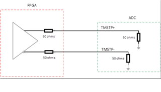
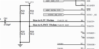
Do you have any recommendation for biasing the TMSTP+ signal on ADC12DJ5200RF?
Non-differential setting.
Also the Which Voltage should it be biased with if any specific is required?
Thanks.
Regards,
Hi sir,
Do you have any recommendation for biasing the TMSTP+ signal on ADC12DJ5200RF?
Non-differential setting.
Also the Which Voltage should it be biased with if any specific is required?
Thanks.
Regards,