


Hi guys.
We are using ADS131M08 ADC. XTAL1 connected to external quartz resonator at 8.192 MHz
We need read 2000 samples per second (data reading in every interrupt by DATA READY pin).
Registers settings (SPI 8 MHz):
I (1327) ads131_read_reg: reg 0x00 val 0x2801 // ID
I (1337) ads131_write_reg: reg 0x03 val 0x3f12 // CLOCK: use 6 channels, oversampling 2048
I (1337) ads131_read_reg: reg 0x03 val 0x3f12
I (1347) ads131_write_reg: reg 0x02 val 0x110 // MODE: clear reset bit in STATUS register
I (1347) ads131_read_reg: reg 0x02 val 0x110
Interrupt handler:
uint32_t adc_int_counter = 0;
int32_t tempvals [6];
int32_t tempvals2 [6];
static void gpio_isr_handler (void * arg)
{
  adc_int_counter++;
  extern uint16_t ads131_status;
  // function send&read ADS131 frame (3 * 10 byte): STATUS register + converted to signed 32 bit MEASURES for 6 channels
  ads131_read_measures (&tempvals[0]);
  if (adc_int_counter<10)
    ads131_read_measures(& tempvals2 [0]); // additional reading for clear ADC internal FIFO after start
}
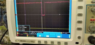
nDRDY signal:
yellow - DATA READY
red - SPI CS
Sometimes nDRDY signal becomes incorrect (1 us peaks instead of meander) (status register value 0x13f):
nDRDY correct if generate only 1000 samples per second (OSR 4096).
The signal is valid if use the following handler:
static void gpio_isr_handler (void * arg)
{
  adc_int_counter++;
  extern uint16_t ads131_status;
  ads131_read_measures (&tempvals[0]);
  if (ads131_status & 0x3f) !=0)
  {
    ads131_read_measures (& tempvals2 [0]);
    adcDataEqual = memcmp(tempvals, tempvals2, sizeof(tempvals)); // !!! STRANGE: WHY DATA IS EQUAL !!!
  }
}
Correct nDRDY signal:
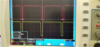
Incorrect nDRDY signal:
Why do the DRDY0-DRDY5 bits of STATUS register appear again despite the permanent reading data in interrupt? And why second read data equel first read?
Why does the nDRDY incorrect when only one reading in interrupt?

