This thread has been locked.

If you have a related question, please click the "Ask a related question" button in the top right corner. The newly created question will be automatically linked to this question.

ADS124S08EVM: Data Conversion Suddenly Stops/Large Readings on Input

Part Number: ADS124S08EVM
Other Parts Discussed in Thread: ADS124S08

Hello, 

Some background on my design:

I am using an ESP32 to interface with an ADS124S08 ADC module. I am using the EVM, so I jumped JP1 to avoid using the onboard processor and have tied the appropriate SPI and GPIO pins between the ESP and the ADS. I have a variable voltage divider circuit running from the 3.3V output pin of the ESP as the input to the ADC at analog input A10 on block J9. The highest voltage this port will see is half of 3.3V or 1.65V, so I know I'm operating within the input range of the ADC. I am also using the internal 2.5V reference and have configured the appropriate jumpers accordingly. I have probed around the EVM's pins and test points to verify that the appropriate voltages appear in their places. The ADC is set to sample 20 SPS in continuous-conversion mode. 

My problems begin when I try to start reading the ADC's conversion results. The entire configuration phase goes very smoothly and the ADC starts sampling. However, its sampling behavior is very finicky. Sometimes it runs for a long time, other times the program stalls almost immediately after taking its 3rd or 4th sample. What I notice is that when I power up the EVM, the red LED turns on. This LED turns off when sampling begins and stays off so long as there is a steady output stream on my serial monitor reporting the values of the samples being taken. When the program stalls however, I notice that this red LED turns back on. 

I'm hoping this LED can indicate whether this is an issue on the software end of the design or if I did something incorrectly with the configuration of the reference/power of the ADS EVM. 

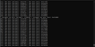
Another issue I am noticing is that the value read after DRDY is pulled low and 24 SCLK cycles are sent is past the cap defined in the ADS124S08 datasheet (0x7FFFFF), which obviously doesn't make sense. Does the input from which data is read have to be configured in the configuration software or does the ADC somehow only read the data on the channel a new conversion is available on? I don't recall seeing something about this in the datasheet, but maybe I didn't look hard enough. An image is attached to show the large ADC readings and the mid-conversion stall.


I would appreciate any help/feedback, thank you in advance for your time and help! 

- Denis

  • Hi Denis,

    When developing the EVM as an afterthought we added the JP1 jumper so that the onboard Tiva could be held in a reset state so that an external processor could be used to control the ADS124S08.  There should also have been some additional pullups and pulldowns used on various pins and connections.  When JP1 is installed the only effectively driven LED is D4 which is indicating power.  While the Tiva is in reset, the GPIO pins are in a high impedance state and the LED drivers for D1-D3 have essentially a floating input.  So the LEDs might be on, off or change state and this could be different from EVM to EVM.

    The same is true for the ADS124S08 START pin and RESET pin.  Both of these pins must have a valid logic level on these pins.  Normally the Tiva would supply these pins with the correct logic voltage levels, but when the Tiva is in reset there must be external voltages supplied to the correct levels.  If these pins are floating, then there can be erratic behavior of the device.

    The output of the ADS124S08 is binary 2's complement and the ADC is always measuring differentially with AINP with respect to AINN.  If AINP is greater in voltage value than AINN then the result is positive (0x to 0x7FFFFF) however is AINN is greater in voltage than AINP then the result is showing as a negative result (0xFFFFFF to 0x800000) where 0x800000 is negative full scale and 0xFFFFFF is one code below 0 (-1d).  The results you are showing are negative code values.

    You must also make sure that you have a good ground connection between the micro you are using and the EVM.  Also any ESD or EMI/RFI pickup on the wires between the EVM and the micro could reset the ADC.  You can confirm if this has happened by reading the configuration registers to see if something has changed.

    Best regards,

    Bob B

  • Hi Bob, 

    Thank you for your reply. 

    I'm not using the START and RESET, pins, so I tied them to DGND and IOVDD, respectively. 

    I probed the input port (A10) to the ADC and am reading positive voltages only. Perhaps my mistake might have something to do with the endianness of the ADC? Is the ADC module little or big endian?

    I will try the method of printing out the config registers. 

    Thank you for your help so far!

    Sincerely, 

    Denis

  • Hi Denis,

    The data format for the SPI serial communication is MSB first.  The endian format relates to how the memory is stored on the micro.  I would suggest that using an oscilloscope or logic analyzer is the best method for checking proper communication and that you are capturing the data correctly when comparing to your code..

    Best regards,

    Bob B

  • Hi Bob, 

    My mistake, that was a silly question. Thank you for the clarification. 

    In regards to the printing of config registers, I didn't notice any changes in the configuration registers between RDATA calls, so I don't believe that the ADC is being reset. 

    I will continue to investigate, thank you for your help!

    Sincerely, 

    Denis

  • Hi Bob, 

    I thought you might want an update. Turns out the START pin was the culprit because its connection to ground was unstable. 

    Thank you again for your help!

    Sincerely, 

    Denis