This thread has been locked.

If you have a related question, please click the "Ask a related question" button in the top right corner. The newly created question will be automatically linked to this question.

ADS131A04: sample holder and sample rate

Part Number: ADS131A04

Hello,

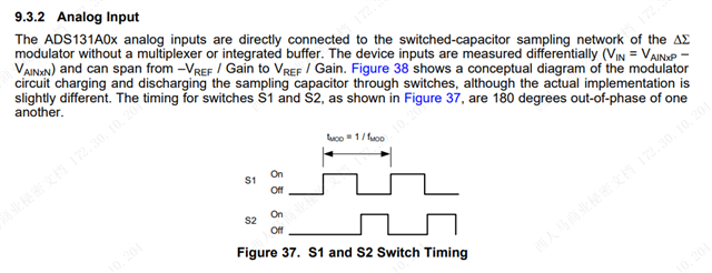
The sample holder sampled at a frequency of fMOD (4.096 MHz), which means the sampling time is only T_mod/2 (approximately 0.122uS), as described in ADS131A04 Manual 9.3.2 (as shown in the figure below). If the sampling capacitance is 24 bits accurate during this time, the output impedance of the input is small to meet the requirement.

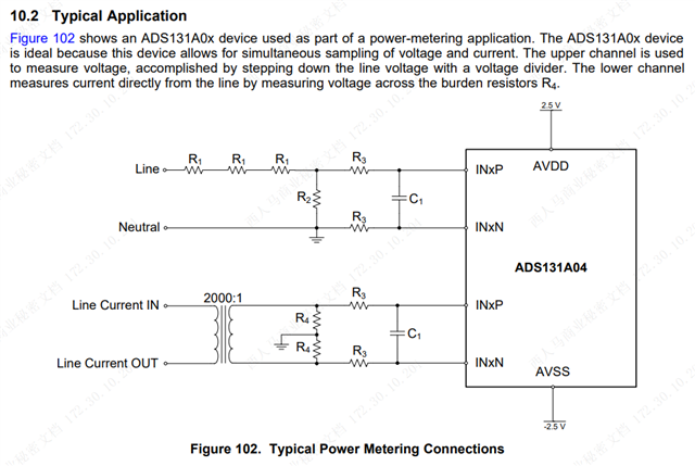
However, in accordance with the typical application 10.2 in the manual (shown below), where R3=100Ω and C1=2.7nF, as input RC, should not achieve a sampling capacitance of 24bit (or even 20bit) accuracy over the time of T_mod/2. The  training:

https://training.ti.com/ti-precision-labs-adcs-introduction-sar-adc-front-end-component-selection

Is there a misunderstanding about the sample retention process or sample time for the ADS131A04?

Best regards

Kailyn

  • Hello Kailyn,

    Thank you for your post.

    Your understanding of the input sample-and-hold circuit is correct. However, the design criteria for a delta-sigma ADC input can be different than that of a SAR ADC input. For many delta-sigma ADCs, the goal of the input circuit is not to settle to less than 1/2 LSB since this becomes impractical for a converter with 24-bit resolution and an LSB size of 10s or 100s of nV. Other error sources such as thermal noise tend to be more dominant. As long as the settling errors at the input frequencies of interest are below this noise level, a delta-sigma ADC system will perform quite well.

    That said - delta-sigma converters which do not have an input buffer often present a lower input impedance in the 5k - 20kohm range that can be challenging to drive. The ADS131A04 has a slightly larger nominal input impedance of about 130 kOhm at fMOD = 4.096 MHz and increases as the fMOD frequency is reduced, so this makes the input drive circuit less challenging. The voltage divider output or CT output signals generally interface directly with the ADS131A04 in grid and e-metering applications, requiring nothing more than a larger R-C circuit used as an antialiasing filter.

    Best regards,

    Ryan