A related question is a question created from another question. When the related question is created, it will be automatically linked to the original question.
If you have a related question, please click the "Ask a related question" button in the top right corner. The newly created question will be automatically linked to this question.
In my project i am using ADS1256 with RPI and i don't now how to set SPI speed to get 30k samples per second can anybody help me to get out of this problem.
Can you help us understand what you have done to try to change the speed and how it has not worked? Have you made sure your ADC is communicating correctly? Have you tried reading back the registers to check if what you are sending is being received by the ADC? Have you tried changing other registers to see if they work i.e. is it only the data rate you are having trouble with or is it all registers? Are you getting any response from the ADC at all e.g. DRDY pulses?
It helps to provide step-by-step, detailed information on what you have done and what happens during your tests so we can help you diagnose the issue.
Yes bryan i change data rate in coding part into 2.5sps and i got 2-3 samples and similarly i made changes to get more number of samples and when i mention 1000 samples its 700-750 samples and again if i increase the data rate still its same. Next i changed SPI max speed to 3840000 HZ but no use.
here one more thing w i want to mention every time when i run the code once it can read 700 samples and once it can read 900 samples so i could not assume how much samples for different time of intervals when i run my code.
Do you have logic analyzer to show us how the SPI communication is functioning? It would be very helpful to see how commands are being sent to the ADC and how the ADC is responding. This will not be obvious simply by looking at the code.
Are you watching for DRDY transitions (high to low) to know when new data is ready?
today i connected the DRDY pin to logic analyzer and DIN and i am DSO so only two channel can be connect at a time since when i run the code i got this and i can't able to find the data i available when DRDY pin at low.
1.Can you mention the basic steps which i need go follow in my code to read the data??
2.i got a doubt that my RPI is communicating with ADS1256 so i did loopback test to read and write a dummy data but here again i got doubt for loopback test i should connect MISO AND MOSI pins of RPI or RPI and ADS1256 MISO,MOSI pins ??
I am not sure what that data on the scope is supposed to represent, but it is clearly bad.
Are you using multiple boards e.g. an ADS1256EVM and a Raspberry Pi board? If so please ensure that there is a strong ground connection between the boards, otherwise errors like the ones you are showing here can result.
To read data, you should be sending the SYNC/WAKEUP commands or toggling the SYNC pin. Please follow datasheet directions for the method that you choose.
You then wait for DRDY to drop low in order to know when new data is available. You then clock out that data using the RDATA command. If you want to switch the mux, do so at this time. If you are continuously converting on one channel, you would just wait for DRDY to drop low again.
Please carefully read the ADS1256 datasheet before proceeding. All of this information is described in detail.
i am using ADS1256 not ADS1256EVM and i followed the procedure which you have mentioned and if i change the sample rate it reads upto 1450 samples per second and but the reading data was not correct its a garbage value again if i choose lesss sample rate and less SPI speed then i can get proper values .
ok i will try to get proper waves in logic analyzer and i will update you .
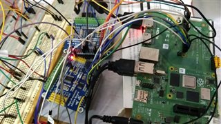
this is my project set up and i gone through the datasheet and i have used input multiplexer MUX register mode to read the data
1.i just write a loop to wait till DRDY pin goes low
2. once DRDY pin is low and i write a register with respect to different channels for example 01h for AIN0,AIN1 and 23h for AIN2 &AIN3 ...etc.
3.then immediately i have sent SYNC and WAKE CMD to sync and i have delay 0.2ms then i sent RDATA CMD to read and put into buffer and which is returned by main loop so till i didn't get correct output and one time it will run and some time it failed to read the device ID itself.
I will be honest, I am not sure you can expect decent performance out of your system with a setup like the one you have shown. All of these jumper wires can potentially pickup noise, etc., that affects the entire system. Actually isolating the source (or sources) of the problem will be very challenging. In fact, the source of the issue is likely the wiring itself, which could only be remedied by building your system on a single PCB.
I don't know how much more support I can offer until the system is cleaned up. There are just too many variables here.
yes bryan still PCB in production so thats why i followed this way but its ok. But what i followed the procedure points its right or wrong and should i need to do some more things.
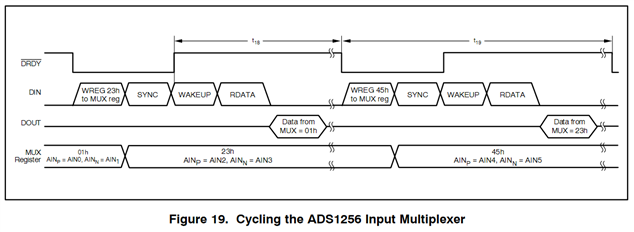
The process to cycle through the inputs and read data is explained step-by-step on page 21 in the ADS1256 datasheet. I have also copied the image that shows the process below. I cannot restate this information any better, so I just point you to the appropriate datasheet text.
Following this procedure will enable you to get data out of the ADC at the throughput specified in Table 14, assuming the timing considerations from page 6 are followed. As mentioned however, the board likely needs to be heavily modified before you can realize this performance from the ADC.