This thread has been locked.

If you have a related question, please click the "Ask a related question" button in the top right corner. The newly created question will be automatically linked to this question.

ADS1298R: Respiration circuit with CF-type applied parts

Part Number: ADS1298R

Dear TI team,

I am implementing the respiration feature on an 18-lead ECG.

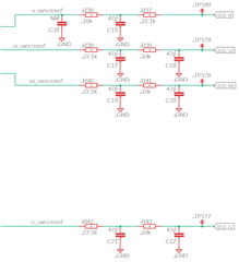
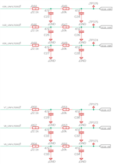
The ADS129xR datasheet (SBAS459K –JANUARY 2010–REVISED AUGUST 2015) recommends a value of 470pF for C1 and C5 (chapter §10.2.1) while the ADS1298R evaluation board recommends a value of 2200pF for the same capacitors called C99 and C100.

Also, there are two main differences between the datasheet circuit and ours:

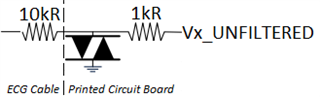
  •  defibrillation protection is implemented using 10kR for each electrode path on the ECG cable, a TVS (MAX30034, Maxim) and 1kR on each electrode path on our PCB.
  • the device is an ECG so the applied parts are CF-type and the maximum allowed total current inside the patient is 10uA (No Fault Condition): taking into account the impact of lead-detection, I would like a maximum respiration current of 8uA. It leads to R1=R2=140kR instead of 40.2kR (chapter §10.2.1 of SBAS459K).

We performed some tests on the ADS1298R evaluation board as well as in our circuit.

On ADS1298R performances with a respiration simulator (Prosim 8, Fluke), we obtain best performance at 32kHz, gain 1 and 112.5°.
Still, the respiration signal is not exploitable with a baseline of 2000R and a 0.1R-variation with any software configuration
With our circuit, same result.

Which value shall be chosen for C1, C5 ?

Can you confirm that R1 and R2 shall be set to 140kR to obtain a respiration current of 8uA ?

Do you still recommend at 32kHz a gain of 3 or 4 and a phase of 112.5° or 135° (page 91 of SBAS459K) ?

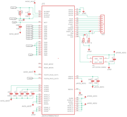
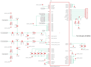
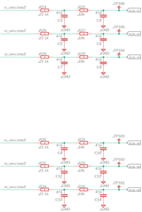
PS: You can find attached our circuit that respects all the guidelines from the datasheet.

  • Hello,

    Due to Thanksgiving holidays in the US, our response is delayed. We shall get back to you by next week.

  • Hi Paul,

    Sorry for the delay in the response, and thanks for the patience.

    The use of C1 and C5 depends on the respiration application design. The high-pass filter of C1/C5 (470pF or 2200nF) and R5/R6 and R4/R5 will help minimize the coupling of ECG waveform on the respiration signals. The factors for choosing the optimum C1/C5 value depend on many factors such as the respiration modulation frequency, respiration phase, gain setting, and LP/HR mode. Our experiments show 470pF is the value best for the application circuit in the datasheet.

    The use of 140kR for R1 and R2 will give approximately 8-9uA of respiration current. Please note that you will need to include any protection resistor and ECG cable resistance (10kOhms) on the respiration path for your calculation.

    For Figure 100 in the datasheet, a gain of 3/4 and phase of 112.5/135 is recommended for the 32kHz respiration modulation frequency using the respiration application shown in Figure 99. However, it may not be optimum for other respiration settings.

    Thanks

    -TC

  • Dear TCT,

    Thank you for your message.

    Respiration current

    The use of 140kR for R1 and R2 will give approximately 8-9uA of respiration current. Please note that you will need to include any protection resistor and ECG cable resistance (10kOhms) on the respiration path for your calculation.

    => With R1=R2=140kR, and 10kR+1kR on each channel for defibrillation => Imod=8.25uA

    Respiration circuitry

    I understand that respiration parameters need to be fine tuned (gain, phase, frequency).

    Can you confirm that the circuit is fine to you assuming that resistors/capacitors can/will be modified ?

    We would like to launch the manufacturing of prototypes.

    Thank you for your help,

    Best Regards,

    PA

  • Hi Paul,

    The schematic for the respiration looks fine. 

    Thanks

    -TC