This thread has been locked.

If you have a related question, please click the "Ask a related question" button in the top right corner. The newly created question will be automatically linked to this question.

ADS1262: Unexpected voltage, and noise, from bias resistors

Part Number: ADS1262

I have a thermocouple measurement design using the ADS1262. The design is based on the evaluation boards for the ADS1262 and ADS114. In addition to those base designs I also have an ADS707 differential analog mux.

For testing purposes I am not cycling through any of the ADC channels.  I have the ADC set to 100sps, continuous, and I have confirmed that the microcontroller is reading these samples fast enough.

If I enable the internal pull-up/pull-down resistors I find a couple strange issues:
* With the input shorted I see measured value of ~2mV. Shorting the input series resistors drop this down about 1mV each. This make it seems like there is a bias current on, and not the bias resistor.
* If I un-short the input I find that the positive rail is pulled to 2.5V and not 5V (which is what VCC is)

If I don't enable the bias resistor, and I short the input, I see normal values (I think). Something less than 90uV.

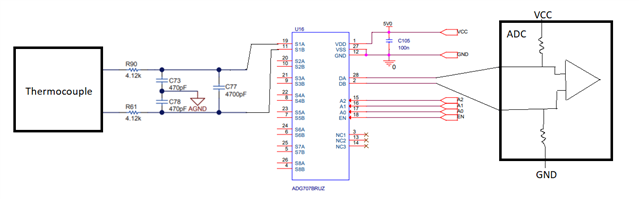
The figure below is a simplified version of the schematic:

  • Hi Jameson,

    When you say that you are shorting the inputs, where are shorting them in the above diagram? You mention at least two locations, can you please explain how the circuit looks for each test?

    With the input shorted I see measured value of ~2mV. Shorting the input series resistors drop this down about 1mV each.

    Also, what is the goal of these measurements? Are you simply trying to establish a baseline for thermocouple broken wire detection? You should not enable the burnout detection features (resistors or current sources) during a precision measurement, this should only be completed in a separate diagnostic measurement cycle. This is because the burnout detection adds some error to the measurement, though this is not relevant to actually detect a broken wire.

    You can also reference our thermocouple circuit design guide for more information: https://www.ti.com/lit/sbaa274

    -Bryan

  • Hey Brian, thanks for the reply.

    When I said 'shorted the input', I mean that I replaced the thermocouple with a shunt.  When I said "shorting the input series resistor" I mean that I shunted pins 1 and 2 of R90 and/or R61.

    The goal of the measurement is to get actual temperature measurement, not just burnout detection.  I thought I needed to enable the bias resistors in order to keep the thermocouple in the measurement and PGA range of the ADC, like the figure below (but using the internal bias resistors).

    Looking at the schematic for the ADS114 eval board I see that they included external bias resistors.  While I included pads in my design to add those, I did not populate them because I thought the internal bias resistors would be sufficient.  The value of R71 and and R72 is 10Mohm in that design.

  • Hi Jameson,

    You can see in Figure 20 from your last post that the bias resistors are right near the input terminals. Importantly, they are added into the circuit before the filter and before the mux. Enabling the ADS1262 integrated resistors creates a current that flows through the mux resistance and both filter resistors, adding an offset error. This error is likely small, but since a thermocouple voltage is also pretty small (10s of mV), the error could be significant. I presume there is a way to calibrate out the initial error as it should just show up as an offset, but it likely has a temperature dependency that would be very difficult to calibrate out. I also could not comment on the variation in the ADS1262 internal pull-up resistors, since this is not really how they were intended to be used.

    If you want to use pull-up/pull-down resistors I would recommend adding them in discretely as per Figure 20.

    Let me know if you have further questions about this.

    -Bryan

  • Thank you Brian, that makes perfect sense.  I'll populate the bias resistors per figure 20.