This thread has been locked.

If you have a related question, please click the "Ask a related question" button in the top right corner. The newly created question will be automatically linked to this question.

AFE5818: AFE5818 data error

Part Number: AFE5818

HI, AFE5818 engineers:

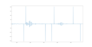
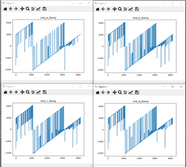
In my own AFE5818 hardware system, the AFE5818 samples at a rate of 12-bit and 80MHz. In actual use, errors will occur in the received echo data, as shown in the figure.  These values ​​should be close to 0, but their absolute values ​​are above 2000. The following figure shows the wrong values: -2046, 2040, -2046, -2046, 2028, 2031, -2047.

  • Hello,

    I am Abhishek and I will help you solve this issue. 

    First cut, it seems that some codes are hitting full range saturation, that is close to +/- 2^11. Can you please share more information about the settings like what blocks you are using in the device. Do you see any pattern in the error? I will share this with my team and discuss about it. Meanwhile I would appreciate if you could provide more information about the test case, such as what are the digital processing blocks you are using, etc. We can then figure out from where this issue is coming from.

    Also, did you check with any other device? Is it happening on others as well.

    Thanks and regards,

    Abhishek

  • Also, I am suspecting that there could be potential capture issue or timing violations in the FPGA capture. Can you try capture the test mode in the device. such as ramp pattern mode and see if you see these glitches in the ramp as well. If so, then it is most likely data capture issue.

    Thanks & regards,

    Abhishek 

  • Hi Abhishek, thanks for your reply.

    I just tested the Ramp pattern and the results are as shown in the figure. The problem is much more serious than the actual test before. It can be seen that the problem is in the digital part rather than the analog part. Most likely, there is a problem with the TIMING of FPGA. Do you have any possible suggestions

  • I would like to add more information:

    1. In different channels, the probability of error is different. Some channels have more errors and some have less errors.

    2. If the data changes little, the error probability is small. If the data changes frequently, the error is more serious, for example, the error of ramp mode is more obvious.

    3. It is mainly because the first bit has errors, and the number of errors is close to + / - 2 ^ 11.

    4. DCLK and fclk are connected with 100 Ω resistance, and the 16 channel data interface is not connected

    I checked the FPGA timing. My processing of each channel is the same, but the error conditions are different. Is it possible that the problem lies in the PCB and the high-speed LVDS data changes in the line?

    Do you have any suggestions

  • I have solved the problem. Impedance mismatch occurred in high-speed LVDS signal, which resulted in digital signal deformation. I added 100Ω matching resistance inside FPGA, and the problem was solved