This thread has been locked.

If you have a related question, please click the "Ask a related question" button in the top right corner. The newly created question will be automatically linked to this question.

ADS1278: How to daisy chain 3 1278 EVMs and then connect to a single uP

Part Number: ADS1278
Other Parts Discussed in Thread: ADS1274,

hi,

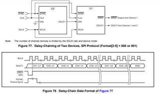
My design daisy chains 3 ADS1274 in dynamic mode. I want 3 channels from each device, so channel 4 is powered down - permanently with on-board connections. It runs in Low Power Mode, ADC and SPI clocks are 5.12 MHz. Want to use the EVM boards to get a head start on code development. Our processor is STM32L.

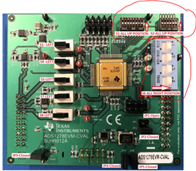
I have 3  ADS1278 EVM systems. How can I daisy chain these and then connect to the STM32L SPI? Mostly interested in routing power to the 3 ADS1278EVM-CVAL's properly and powering down channels 4 thru 8. Can I do all this with jumpers? Do I need all 3 MMB0?

Don't need a detailed connection drawing. Just to know if what I want to do is possible and any tips to help me along.

If daisy won't work, I could just take 8 channels from a single EVM. Not the 9 I want, but other than that, would there be any difference apparent to my STM code?

mark

  • Hello Mark,

    Yes, you should be able to connect three boards in daisy-chain configuration, and enable 3 channels on each board.  Section 3, Quick Reference, in the User's guide provides more details.

    As long as you do not connect the MMB0 board, you can use the dip switches, S1 and S2, to power up/down each channel, and configure the operation mode.  In order to use SPI mode, S6 should be set to the Left position so that the SPI interface is available on header J4.

    You will need to provide external power to each board; Table 4 provides details as well as the included schematics in Figures 12-15.

    AVDD = 5V x 0.145A = 0.725W

    DVDD = 1.8V x 0.030A = 0.054W

    IOVDD = 3.3V x 0.001A = 0.033W

    Also, since you want to use daisy chain mode with 3 separate ADC's, all ADC's will need to be synchronized so that conversion data is available at the same time for all 9 channels.  This will require using the /SYNC pin, J4,pin1 and a common clock source, which can be the same frequency as SCLK. 

    Please note that in SPI mode, the CLK must be continuous, but SCLK only needs to be active when retrieving data.  In one transfer frame, you will need to clock 24*N channels, or for 9 channels, a total of 216 CLK's.  After the ADC's are synchronized, the MCU only needs to monitor a single /DRDY line from one of the 3 ADC's (can use an interrupt input), and then use the SPI port to clock out 216 bits.

    Please note that you may have signal integrity issues using jumper wires between multiple boards.  If this occurs, you can probably slow down the clock for software development purposes.

    Have a nice weekend.

    Regards,
    Keith Nicholas
    Precision ADC Applications

  • Thanks, that's what I wanted to know.

    mark