This thread has been locked.

If you have a related question, please click the "Ask a related question" button in the top right corner. The newly created question will be automatically linked to this question.

TSW14J56EVM: Auto Rearm Binary File Data

Part Number: TSW14J56EVM
Other Parts Discussed in Thread: ADC12J4000

Hi,

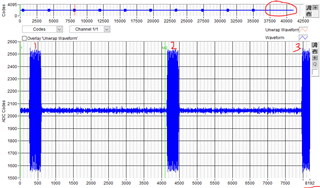
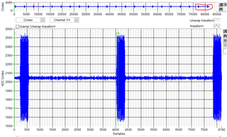
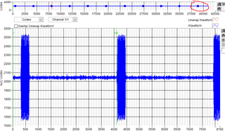
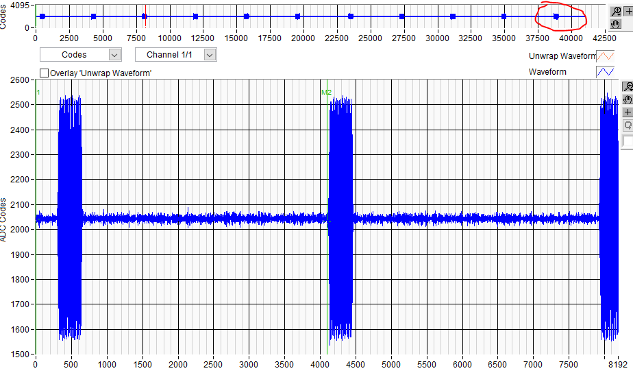
I'm using the TSW14J56EVM in combination with the ADC12J4000, and I'm running into a number of issues. I'm using the ADC to capture 100 ns RF pulses that are repeated every 6.25 ms. I have a RF Pulse detect circuit that externally triggers the TSW14J56EVM with ~10ns delay. The system is setup to auto rearm, and trigger on the rising edge. The triggering appears to work well (I send 10 pulses, and the ADC receives 10 pulses, tested up to 24000 pulses with good agreement). When I check the data though (binary file out), I'll get the right number of pulses followed up by garbage at the end, as well as a mismatch between the number of samples per trigger that I expect to see.

I've attached a slide deck with some captures of what I'm seeing.

CaptureIssue.pptx

Also on a side note, the MATLAB Automation library seems to be missing the Auto ReArm methods despite being visible in the .h and .lib files opened as a text. I've attached a command line output from matlab when I try to run the method as well as a print out of what MATLAB finds in the library.

ERROR CALLING METHOD: ADC_Auto_ReArm_Trigger_Settings

Error using calllib
Method was not found.

Error in HSDCPro_Test (line 210)
    [Error_Status] = calllib('HSDCProAutomation_64Bit','ADC_Auto_ReArm_Trigger_Settings',...


Printing all the lib functions:
>> libfunctions('HSDCProAutomation_64Bit')

Functions in library HSDCProAutomation_64Bit:

ADC_Analysis_Window_Length        DAC_Send                          Read_DDR_Memory                   
ADC_Average_Settings              DAC_Tone_Generation               Read_Registers                    
ADC_Channel_Power_Parameters      Disconnect_Board                  Reset_Board                       
ADC_Channel_Power_Settings        Download_Firmware                 Save_FFT_As_PNG                   
ADC_Plot_Type                     FFT_Window                        Save_Raw_Data_As_CSV              
ADC_Save_Raw_Data_As_Binary_File  FFT_Window_Notching               Select_ADC_Channel                
ADC_Test_Selection                Generate_Software_Trigger         Select_ADC_Device                 
Automation_DLL_Version            Get_ADC_Device                    Select_DAC_Device                 
Connect_Board                     Get_DAC_Device                    Set_ADC_BIM                       
DAC_Active_Channel                Get_Error_Status                  Set_ADC_Input_Target_Frequency    
DAC_Channel_Enable_Settings       Get_FFT_Data                      Set_Number_of_Samples             
DAC_Data_Rate                     HSDC_Ready                        Single_Tone_Parameters            
DAC_Load_File                     LVDLLStatus                       Trigger_Option                    
DAC_Option                        Pass_ADC_Output_Data_Rate         Write_Registers                   
DAC_Preamble                      Pass_Capture_Event                

Thanks,

Chris

  • Actually I just found the error with the MATLAB Automation library, the sample provided in the Automation folder references the following folder:

    C:\Program Files (x86)\Texas Instruments\HSDC Pro Dual Capture Automation\Source Code\HSDC Pro Matlab Automation

    This directory has its own HSDC Pro Library which was appears to have an older version of the library. When I updated the reference to the proper folder:

    C:\Program Files (x86)\Texas Instruments\High Speed Data Converter Pro\HSDCPro Automation DLL\64Bit DLL

    All the methods are found.

    I am still encountering the same issue w.r.t the pulse captures.

    Thanks,

    Chris

  • Chris,

    We are checking with the software team regarding this. The capture issue may be related to the fact that every time HSDC Pro does a capture, the JESD link gets re-initialized. There is an option around this.

    After establishing a valid ADC and FPGA link, you may need to use a new ini file with the command "skipreconfig = 1" included to avoid interrupting the JESD link between the ADC and FPGA. By using a new ini file with the command "skipreconfig = 1" at the end, every time a capture is issued, the link will not be re-initialized. 

    Attached is an ADC12J4000 ini file with this command added. You would need to place this in the following directory if you plan on using it:

    C:\Program Files (86)\Texas Instruments\High Speed Data Converter Pro\14J56revD Details\ADC files.

    You will have to use the original ini file to get the link established. After this, switch to the modified ini file.   

    Regards,

    Jim

    https://e2e.ti.com/cfs-file/__key/communityserver-discussions-components-files/73/ADC12J4000_5F00_BYPASS_5F00_skip_5F00_reconfig.ini 

  • Thanks for the reply. So I've tried alternating between these two ini files, with the highlighted main differences between your original file:

    1) Auto Re Arm:

    - Interface name="TSW14J56REVD_ADC_DDR_DAC_BRAM_256KB_XCVR_FIRMWARE"

    - JESD IP LMFC Realign=1
    - Trigger Input Polarity Selection = 1

    2) Auto Re Arm + Skip Reconfig:

    - Interface name="TSW14J56REVD_ADC_DDR_DAC_BRAM_256KB_XCVR_FIRMWARE"

    - Skip Reconfig = 1
    - JESD IP LMFC Realign=1
    - Trigger Input Polarity Selection = 1

    Both of them perform identically. I've also tried setting the "JESD IP LMFC Realign = 0" and that also produces the same results.

    I've noticed If I capture 10 triggers from a fresh firmware switch (moving from a .ini file that has 'Interface name="TSW14J56REVD_FIRMWARE"' to 'Interface name="TSW14J56REVD_ADC_DDR_DAC_BRAM_256KB_XCVR_FIRMWARE"'), the recording won't have any noise/pulses in the last 6% of the sample or so (see the red circle in the drawing below). However, it will still have too few samples per pulse - there are 3 pulses recorded within 8192 samples when there should only be 2.

    Then if I jump to recording 20 triggers, and then back to 10 triggers I get the following:

    20 triggers test - 22 pulses recorded (extras highlighted in red circle):

    10 trigger test - 11 pulses recorded this time around (extra highlighted in red circle):

    So there's definitely something not being cleared between each capture/trigger test, that is properly cleared after a firmware reset. And then there's also something wrong with the number of samples being recorded per trigger, with the remaining amount of samples being pulled from a buffer that wasn't cleared.

    Thanks,

    Chris

  • Chris,

    We are trying to duplicate this issue.

    Regarding the issue with Automation DLL location, the path mentioned is the path of the HSDC Pro DLL used in the older version of the application,

     “C:\Program Files (x86)\Texas Instruments\HSDC Pro Dual Capture Automation\Source Code\HSDC Pro Matlab Automation”

     The correct path of the DLL for latest 32Bit HSDC Pro is,

     “C:\Program Files (x86)\Texas Instruments\High Speed Data Converter Pro\HSDCPro Automation DLL\64Bit DLL”

    Regards,

    Jim

  • Chris,

    Our software team reply:

    "We can reproduce this issue with the existing TSW14J56 setup. The issue happens randomly, and it is only with the samples that are captured for the last trigger. If the samples are captured for n triggers, then the nth trigger samples would be some old data,  and the other trigger samples are proper.

    We tried several things in the software part to make some improvements for this, but we couldn’t bring it to work as expected. Since it is occurring only at the last trigger, one workaround will be capturing for one additional trigger and discarding the last trigger data captured.


    Issue 2: Mismatch between the number of Samples

    We are not able to reproduce this issue. We tested with the available setup using a Ramp, and we get the correct number of samples for each trigger, and the Ramp continuity will be affected between triggers. 

    Regards,

    Jim

  • I'll try providing inputting a ramp function to double check this, but I'll have to figure out how to do that on my signal generator/swap signal generators.

    In the meantime, does the software team have an explanation for the trigger behavior I'm seeing in these screenshots?

    Again, the actual pulses sent in are 100 ns wide, 6.25 ms apart (i.e. each trigger capture is 6.25 ms apart). Each trigger should be 4096 samples and only capture one pulse. In the image above, within 8192 samples (two trigger lengths), I'm seeing almost 3 fill pulses - this is what I mean by possibly a different number of samples per pulse.

    Thanks,

    Chris

  • Chris,

    Here is the latest reported:

    Issue 1: Garbage data at the end

    We can reproduce this issue with the existing TSW14J56 setup. The issue happens randomly, and it is only with the samples that are captured for the last trigger. If the samples are captured for n triggers, then the nth trigger samples would be some old data,  and the other trigger samples are proper.

     We were able to observe this when we tried switching between Ramp and sine signal between two Auto Re-arm captures.

    We tried several things in the software part to make some improvements for this, but we couldn’t bring it to work as expected. Since it is occurring only at the last trigger, one workaround will be capturing for one additional trigger and discarding the last trigger data captured.

    Issue 2: Mismatch between the number of Samples

    We are not able to reproduce this issue. We tested with the available setup using Ramp, and we get the correct number of samples for each trigger.

    Regards,

    Jim