A related question is a question created from another question. When the related question is created, it will be automatically linked to the original question.
If you have a related question, please click the "Ask a related question" button in the top right corner. The newly created question will be automatically linked to this question.
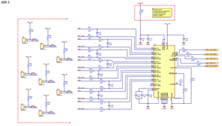
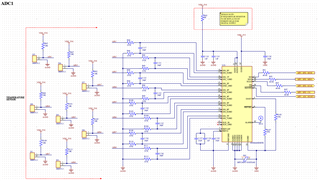
ADS8668: I would like to know if there is any mistake in the connection?
1. I did not see a connection between your AGND and GND and It may be in your other schematic, however a solid ground plane is recommended for both AGND and GND.
2. The AINx_GND should be connected the AGND ground plane, this ADC can only support single-ended input.
3. It's very hard to see if your input capacitor is 10nf or 10uF. If it's 10uF capacitor, the value will be too large.
4. You are pulling up all inputs to the VDD_5V0 with a 10kohm resistor, this will require a clean power supply, otherwise it may affect your normal signal. Also, a 5V normal input can not be converted and it will reduce your dynamic range of ADC. There is another solution you can consider, please refer to the app note: https://www.ti.com/lit/an/sbaa507/sbaa507.pdf
Thanks for your information. A single solid/dedicated ground plane is recommended which is the recommendation in the data sheet. The Alarm is an output, so you can leave it floating if it's not used.