This thread has been locked.

If you have a related question, please click the "Ask a related question" button in the top right corner. The newly created question will be automatically linked to this question.

DAC7760: Output voltage is zero

Part Number: DAC7760

Hi Team,

Our customer reported that he is using DAC7760IPWP during 2 years for industrial DAC device but a few weeks ago he found some error on the output. According to our customer, 

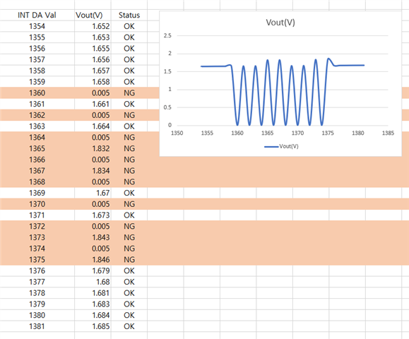
When he sent to setpoint to  33.33% to our device, voltage out measure to Zero. normally it has to be out 1.666V because the device work on 0~5V range.
So I tested it with 4 DAC7760s.
All four chips had identical test results.
It shows the same symptoms when you request output in the same specific section.

I already made 200 Boards for our products.

Attached is the schematic diagram.

Schematic.docx

Regards,

Danilo

  • Danilo,


    I'm not entirely sure what the problem is. However, we do not recommend using the device in the same way as SPI with multiple devices on the bus because the LATCH pin is not really a /CS. With multiple devices connected to the SPI lines, the communication should have the SCLK gated so that the DACx760 does not see the SCLK when communicating with other devices on the bus. Specific bit patterns can cause problems with the watchdog timer and the CRC implementation. Previous versions of the datasheet dating back to January of 2018 specifically say which bit patterns can cause these problems. However, we've recently changed the datasheet to specifically say that the SCLK should be gated. Note - TI has not made any changes to the device recently, and I think the device is the same as when we introduced it in 2013.

    However, this does not look like the same problem that I've described above. I've also looked at the schematic and I don't see anything that I would expect would be a problem. However, this does look a bit like a digital communication problem. The error appears somewhat periodic, as if alternating high and low data points (although of the high data points, there are still bad ones). Does this pattern repeat with more alternating high/low points if the data is take for longer periods of time? Do each of these data points correspond with a write to the device? Does this problem occur with any other analog changes in the board? Can I get a much longer sequence of measured data?

    I would also check to see if there are any changes to the reference voltage while these errors are occurring.

    At this point, I'd just like to gather as much data and description about the problem as I can.


    Joseph Wu

  • Dear Joseph

    When I found this issue, I sent data only with DAC7660 without shared SPI lines. but there is same problems.

    Also, I only wrote one piece of data at a time during the course of the experiment. other range works good.
    I added 10 chips I have and tested them all, but they all show the same result.

    I don't know much about the structure of the chip, but if there is a problem with the switching point in the section inside the chip, can such a problem occur?

    If not, should I suspect a data error passing through the SPI line?

    In the error state, the alarm pin (#3) remains high.
    I will check the reference voltage soon.

    Thanks for your reply.

    PS. VREF ( Pin #14 ) out 5.00V in error state.

  • Todd,


    I'm not sure I understand all of your comments. I need to know what is being sent to the device. When the data is incorrect, what is SPI transaction being sent? Alarm is an active low signal, so ALARM set high means that the device is not detecting a problem. Because the ALARM is high, I don't think this is a problem the CRC or watchdog being accidentally set.

    To look at this you could use an oscilloscope to trigger on the voltage output going to 0V. At the same time, you could look at the DIN, SCLK, and LATCH signals going to the device. Using this method, you could verify the communications during a DAC output setting.


    Joseph Wu