This thread has been locked.

If you have a related question, please click the "Ask a related question" button in the top right corner. The newly created question will be automatically linked to this question.

DAC8775EVM: DAC8775 IC chipping

Part Number: DAC8775EVM
Other Parts Discussed in Thread: DAC8775,

Dear TI,

I recently started using DAC8775 EVM to do few test on Analog output. During my testing, 2 EVM boards gone bad.

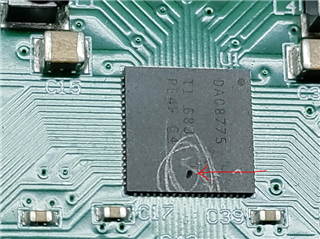
Found a small hole chipping on the DAC8775 IC  on same location for both EVMs. Total 4 EVM are not working, other 2 EVM have different issues. 

Please Find image of DAC8775 chipping.

Board 1:


/resized-image/__size/320x240/__key/communityserver-discussions-components-files/73/pastedimage1639663762617v6.png

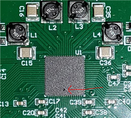
Board 2: (Only 24V Supply to J2, Internal LDO was used with JP11, JP9 and JP13 Removed. No USB Dongle Connected and Jumper setting as per Datasheet) 

Just out off box and this issue happened. 
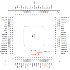
/resized-image/__size/320x240/__key/communityserver-discussions-components-files/73/pastedimage1639663135719v4.png

IC PIn Diagram: 

/resized-image/__size/320x240/__key/communityserver-discussions-components-files/73/pastedimage1639665672955v8.png

Can you please check which circuit is present on this area of IC Die, It will help to understand cause of IC Damage. 

What caused this ?

Thank you,

Manikanta. 

  • Hi Manikanta,

    Generally these types of "holes" can happen if there has been an extreme electrical over stress on the device.  Did you have any load on the output during your testing? Is it possible that you have inverted the -24V supply when you powered up the board? What was the current load on the 24V input during the event?

    thanks,

    Paul

  • Hi Paul,

    I was using No Load for DAC EVM. For power supply i was careful with polarity to EVM, I was using External 24V SMPS to power EVM. 

  • Manikanta,


    This post is similar to another post. Are you working in the same group?:

    e2e.ti.com/.../dac8775evm-boards-spoiled-after-only-a-short-time-using-it-and-spi-lines-are-not-working-properly-after-that

    In that in that post, JP9 and JP11 were installed, while J13 was uninstalled. In that configuration, the DVDD is sourced from the J1 connector and the DVDD power comes from the SM-USB-DIG. I didn't have any issues running the device that way. In your case, you have JP9, JP11, and JP13 all uninstalled. With this configuration, the DVDD power comes from the DVDD LDO on the device. This is the normal DVDD configuration for the EVM. I don't expect any damage from either configuration.

    Now, we still need to check the power supply connection and the digital connections. What are you using for your power supply? Is there a chance that this is somehow over voltaging? The connection should go to J2, but I usually use clip leads and attach power to TP18 (PVDD/AVDD) and some ground test point. Also, is does your power have any current limiting? I will generally power up a board with some sort of current limited power supply just to make sure I've connected everything correctly.

    After that are using the SM-USB-DIG to connect this to your computer and run the GUI? Using the SM-USB-DIG, there is a chance that the dongle and board are offset in connection. I've never damaged the device this way, but it is possible. If the connection is offset, then the GUI will certainly be unresponsive. If you're using a different controller, what are you using? Have you checked output voltages of that connection and see if it is compatible with the device?

    For operation, did device work for a while and then get damaged? Or was the damage immediate? I just wanted to check to see if this is a question of miswiring or if there is some component in configuration.

    Looking the device and the location of the damage, it's hard to know what that section is. It is very close to the reference and AVDD pins. The closest pin looks like the REFGND pin, but I'm not sure if that is the pin or area that is damaged.

    Joseph Wu

  • Hi Joseph,

    Yes we are connected indirectly and both facing different issue. I have 2 EVM Boards with IC chipping and Dinie have 2 EVM Boards with SPI issue.

    1) What are you using for your power supply? i was using 24V SMPS for Board Power, i should have used Power Supply with current limit to protect EVM.

    I checked for SMPS overshoot and undershoot along with ripple factor, all values are correct, tested via oscilloscope.

    2) After that are using the SM-USB-DIG to connect this to your computer and run the GUI? Yes with internal LDO for DVDD, i am connecting SM-USB-DIG to computer and GUI. Even with offset in connection, i don't think chipping is possible. Yes GUI is not working, GUI detects EVM but on RESET, all alarm are HIGH.

    3) If you're using a different controller, what are you using? I am using STM32 controller with SPI lines. STM32 is 3.3V SPI, and DAC EVM SPI is 5V. STM32 can handle 5V SPI line, so i didn't use level convertor.  

    4) For operation, did device work for a while and then get damaged? Yes with Dinie EVM, board worked for some time and later DAC went bad on SPI lines.

    5) I am sure its not because of wrong wiring, I checked connections before each power On

    Thank you.

  • Manikanta,


    To be sure, I suggested the power supply should have a current limit just to make sure that there isn't a problem in the setup. I always do this just to make sure that I have boards setup correctly and just in case there's a problem with shorting an output.

    I would start by using the EVM with the SM-USB-DIG. While the SM-USB-DIG isn't the same as the STM32, it is capable of evaluating the EVM and sending the proper digital signals. I've been using a DAC8775EVM to evaluate some setup questions and to check the efficiency of the buck-boost converter and I haven't had any issues with the board. I suggest using the SM-USB-DIG because I think it's a pretty good controller setup and there won't be any compatibility issues. I would run through some basic setup to make sure you check that the device works the way that you think it does (powering up the device, the reference, and DAC settings) and set some DAC configurations.

    If you still are using the external STM32 controller, I think the 3.3V SPI lines should match the DVDD supply. For that, the DVDD is an input and DVDD_EN should be low so that the DVDD can be a supply input. DVDD's operating range goes as low as 2.7V.

    If Dinie's board was operating for a while and then stopped working, I wanted to know how the board was set up when it was damaged. I may be able get you a couple of replacement boards but I want to make sure you don't repeat the damage.

    After you get the EVM what modifications to jumper settings do you make to setup the board? How do you have the boards connected? Can you put up a picture of the board with your physical connections for power supplies and microcontroller lines? How do you have DVDD connected? Also, how do you first start to configure the device with the STM32? What are the first configurations that you send to the device.

    After the device is powered up and configured, how do you load the device. Are you changing loads? What DAC output settings are you testing?

    Again, I just want to know to make sure you're not damaging more boards. If you send me the information, I can likely reproduce your setup and get it to work.


    Joseph Wu