Hi team,
1、One of our customers has the following questions, could you help me reply
We need register values that match our setting.
The settings for using the DAC37J82 are shown below.
Input Clock : 500Mhz
Input Data rate : 500MSPS
Interpolation :2
Complex mixer enable
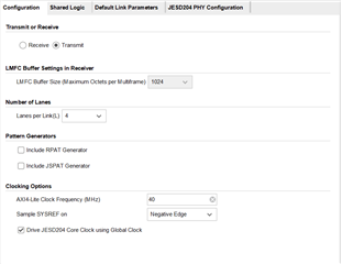
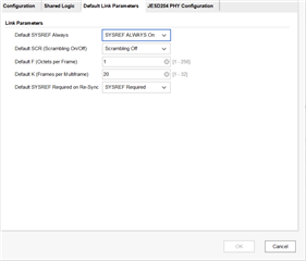
JESD LMFS : 4211
Internal PLL not use.
Please, Check
DacRegWrite(0x00, 0x0118);
DacRegWrite(0x01, 0x0003);
DacRegWrite(0x02, 0x2002);
DacRegWrite(0x03, 0xA300);
DacRegWrite(0x04, 0xF0F0);
DacRegWrite(0x05, 0xFF07);
DacRegWrite(0x06, 0xFFFF);
DacRegWrite(0x07, 0x3100);
DacRegWrite(0x08, 0x0000);
DacRegWrite(0x09, 0x0000);
DacRegWrite(0x0A, 0x0000);
DacRegWrite(0x0B, 0x0000);
DacRegWrite(0x0C, 0x0400);
DacRegWrite(0x0D, 0x0400);
DacRegWrite(0x0E, 0x0400);
DacRegWrite(0x0F, 0x0400);
DacRegWrite(0x10, 0x0000);
DacRegWrite(0x11, 0x0000);
DacRegWrite(0x12, 0x0000);
DacRegWrite(0x13, 0x0000);
DacRegWrite(0x14, 0x0000);
DacRegWrite(0x15, 0x0000);
DacRegWrite(0x16, 0x0000);
DacRegWrite(0x17, 0x0000);
DacRegWrite(0x18, 0x0000);
DacRegWrite(0x19, 0x0000);
DacRegWrite(0x4B, 0x1E00);
DacRegWrite(0x1B, 0x8000);
DacRegWrite(0x55, 0x00FF);
DacRegWrite(0x5F, 0x3210);
DacRegWrite(0x64, 0x0001);
DacRegWrite(0x22, 0x1B1B);
DacRegWrite(0x23, 0x01FF);
DacRegWrite(0x4A, 0x0F1E);
DacRegWrite(0x25, 0x4000);
DacRegWrite(0x26, 0x0000);
DacRegWrite(0x2D, 0x0001);
DacRegWrite(0x2E, 0xFFFF);
DacRegWrite(0x2F, 0x0004);
DacRegWrite(0x30, 0x0000);
DacRegWrite(0x4C, 0x1F03);
DacRegWrite(0x4D, 0x0100);
DacRegWrite(0x4E, 0x0F6F);
DacRegWrite(0x34, 0x0000);
DacRegWrite(0x3B, 0x0000);
DacRegWrite(0x3C, 0x1C28);
DacRegWrite(0x4F, 0x1C61);
DacRegWrite(0x5E, 0x0000);
DacRegWrite(0x59, 0x0000);
DacRegWrite(0x46, 0x1882);
DacRegWrite(0x5A, 0x00FF);
DacRegWrite(0x48, 0x3143);
DacRegWrite(0x5B, 0x00FF);
DacRegWrite(0x24, 0x0020);
DacRegWrite(0x1A, 0x0020);
DacRegWrite(0x31, 0x1000);
DacRegWrite(0x32, 0x0000);
DacRegWrite(0x33, 0x8828);
DacRegWrite(0x3D, 0x0088);
DacRegWrite(0x3E, 0x0128);
DacRegWrite(0x3F, 0x0000);
DacRegWrite(0x47, 0x01C8);
DacRegWrite(0x49, 0x0000);
DacRegWrite(0x58, 0x00FF);
DacRegWrite(0x60, 0x5764);
DacRegWrite(0x4D, 0x0100);
DacRegWrite(0x4E, 0x0F6F);
DacRegWrite(0x50, 0x0000);
DacRegWrite(0x51, 0x00DC);
DacRegWrite(0x52, 0x00FF);
DacRegWrite(0x53, 0x0000);
DacRegWrite(0x54, 0x00FC);
DacRegWrite(0x5C, 0x1111);
DacRegWrite(0x61, 0x0111);
DacRegWrite(0x1E, 0x9999);
DacRegWrite(0x1F, 0x9980);
DacRegWrite(0x20, 0x8008);
DacRegWrite(0x65, 0x0001);
DacRegWrite(0x66, 0x0001);
DacRegWrite(0x67, 0x0001);
DacRegWrite(0x68, 0x7709);
DacRegWrite(0x69, 0x0000);
DacRegWrite(0x6A, 0x0000);
DacRegWrite(0x6B, 0xBD07);
DacRegWrite(0x6C, 0x0007);
DacRegWrite(0x6D, 0x0090);
DacRegWrite(0x6E, 0x0000);
DacRegWrite(0x6F, 0x0000);
DacRegWrite(0x70, 0x0000);
DacRegWrite(0x71, 0x0000);
DacRegWrite(0x72, 0x0000);
DacRegWrite(0x73, 0x0000);
DacRegWrite(0x74, 0x0000);
DacRegWrite(0x75, 0x0000);
DacRegWrite(0x76, 0x0000);
DacRegWrite(0x77, 0x0000);
DacRegWrite(0x78, 0x0000);
DacRegWrite(0x79, 0x0000);
DacRegWrite(0x7A, 0x0000);
DacRegWrite(0x7B, 0x0000);
DacRegWrite(0x7C, 0x0000);
DacRegWrite(0x7D, 0x0000);
DacRegWrite(0x3B, 0x0000);
DacRegWrite(0x25, 0x0000);
DacRegWrite(0x3C, 0x0250);
DacRegWrite(0x3C, 0x0250);
DacRegWrite(0x3E, 0x0128);
DacRegWrite(0x4C, 0x1F03);
DacRegWrite(0x4D, 0x0100);
DacRegWrite(0x4B, 0x1E00);
DacRegWrite(0x56, 0x0000);
DacRegWrite(0x57, 0x00FF);
DacRegWrite(0x00, 0x0018);
DacRegWrite(0x4A, 0x0F1E);
DacRegWrite(0x4A, 0x0F1E);
DacRegWrite(0x4A, 0x0F1E);
DacRegWrite(0x4A, 0x0F01);
DacRegWrite(0x4A, 0x0F1F);
DacRegWrite(0x4A, 0x0F01);
DacRegWrite(0x03, 0xF081);
Thank you.
2、I am not familiar with high-speed ADC and high-speed DAC. I want to learn about high-speed AD / DA, which can more effectively answer customers' questions, but I don't know where to get started. Can you recommend some related learning materials?
Best Regards,
Amy Luo