This thread has been locked.

If you have a related question, please click the "Ask a related question" button in the top right corner. The newly created question will be automatically linked to this question.

ADS1299EEGFE-PDK: Proper power wiring

Part Number: ADS1299EEGFE-PDK
Other Parts Discussed in Thread: ADS1299

I'm having problems reading data from the ads1299 eeg board, specifically the device id.  I'm getting 0, and I'm 

assuming that this is because I'm not properly powered up and/or jumpers are incorrect.

First question, Is there any difference in powering via 3.3V, vs 5V?  I'm currently using 3.3, with a raspberry pi 4.

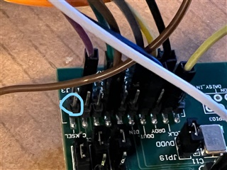
Second question, what is considered pin 1 on block J3 when looking at the board?  Is it the circled pin in the below image, or

the pin behind it?


Current jumper configurations:

JP2: 2-3

JP4: 1-2  (does the jumper need to be removed if using 3.3V?)

JP6: 1-2

JP7: 1-2

JP8: 1-2

JP17: open

JP18: 2-3

JP19: 1-2

JP20: 1-2

JP21: 2-3

JP22: 2-3

JP23: 1-2

JP24: 3.3V power applied to pins 2-3

Is there anything glaringly wrong with this setup?

Thanks in advance

  • Hi Mark,

    Welcome to the E2E forum !!!

    The ADS1299 nominal operation analog power supply is 4.75V to 5.25V and the digital power supply is 1.8V to 3.6V. Please verify that you supply the correct analog power supply to the EVM. You are correct; the square pad of the connector J3 is Pin 1. The CLKSEL label should be on the other side, which is Pin 2.

    The MMB0 board powers the EVM analog power supplies through jumper JP4. If it is left open, there will be no analog supplies for the EVM. Please use the test points on the EVM to verify the power supplies if you see any issues. I do not see any other issues with the other jumper settings listed. You can also refer to the user's guide for more detailed information on the EVM design.

    Thanks

    -TC

  • Thank you for the response, TC.  I've gone back and rewired to use the 5V power supply from the RPi, via JP4.  Using test point  5 and 8, I can verify that there is 5.19 V running currently.  Using test point 4 and 8, I get -5.19V.  Reading the difference between JP2 and JP20 shows a differential of 5.0V.  So that seems to be good.  

    Now I don't also need to supply the 3.3 Voltage as well, correct?  I'm a bit confused, as page 15 of the User's Guide says:

    "The default power-supply setting for the ADS1299EEG-FE is a unipolar analog supply of 5V and DVDD of either +3V or +1.8V".

    Thanks again for your insight.

  • Hi Mark,

    Both the analog and digital power supplies for the EVM are independent. Therefore, you will need to provide both analog and digital power supplies to the EVM.

    The MMB0 board also supplies the DVDD power supply through pin J4.7 (+1.8V) or J4.9 (+3.3V). The jumper JP24 is used to select the desired DVDD supply for the device. Please refer to the EVM schematic for clarification if you have any doubt.

    Thanks

    -TC