This thread has been locked.

If you have a related question, please click the "Ask a related question" button in the top right corner. The newly created question will be automatically linked to this question.

AMC1106M05: configuration of shunt resistor

Part Number: AMC1106M05

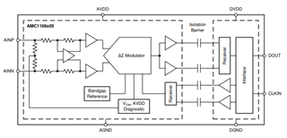
Hello Team, my customer needs support on shunt resistor configuration

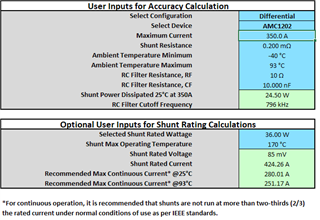
Target is to achieve a measurement range of +/-350A-p (referred to +/-64mV). Shunt selection is difficult because only certain standard values are available. (100/200/300/500uOhm).

For this purpose a 180uOhm would be a perfect fit but preferred is 200uOhm (simpler available). But this means using a voltage divider of 10/90 ratio in front of the input stage.

Now the question:

- In the datasheet there is an input resistor of 4.9kOhm specified. Can this one be used with a 270 Ohm resistor on each input (560Ohm total)?

- Is the accuracy/tolerance of this 4.9kOhm in range of <1%?

- Or is it better to put 560 Ohm at AINP and AINN on GND?

- Other solution would be with a real voltage divider such as 1+20+1 Ohm and connect 20 Ohm at AINP/N?

Many Thanks for any proposal or other ideas to simplify the shunt resistor selection

Josef

  • Hi Josef,

    The AMC1106M05 is a +/-50mV input device, meaning that the specified input voltage range is +/-50mV, but as you pointed out, the clipping voltage is +/-64mV. As per the first link below, we typically recommend not going beyond +/-56mV to ensure a high accuracy measurement, as you risk approaching a nonlinear region. If the accuracy requirements are relaxed at the higher amperages, then this is less of a concern. 

    https://www.ti.com/lit/an/slyt810/slyt810.pdf

    The 4.9kohm differential input resistance is the equivalent resistance of the differential amplifier and common-mode diagnostics circuits on the front end. As per the FAQ link below, this differential input impedance can typically vary +/-5% with 3-σ and 4-σ variations of +/-15% and +/-20% respectively, but there are not min/max specified values for these parameters and variations greater than these levels are possible. Therefor, it is best to treat this as a high input impedance input - which it is when compared to a 200uohm shunt. 

    https://e2e.ti.com/support/amplifiers-group/amplifiers/f/amplifiers-forum/1023946/faq-does-ti-provide-guidance-on-input-resistance-variation-due-to-manufacturing-process-temperature-drift-and-lifetime-for-isolated-converters

    I would recommend adopting the approach you listed in the last bullet point, a real resistor divider between the shunt resistor and the AMC1106M05 which is not an uncommon approach. 4Ohm + 16Ohm would scale the shunt voltage down from 70mV to 56mV. 

    Last but not least, I'd like to remind the customer that for continuous operation, it is recommended that shunts are not run at more than 2/3 the rated current (RMS) under normal operating conditions as per IEEE standards. This excel calculator is intended for accuracy calculations with isolated amplifiers, but the Shunt Rating Calculations portion of the calculator may be helpful to the customer: https://www.ti.com/lit/zip/sbar020

    A 200uohm, 36W shunt with a maximum operating temperature of 170C should work well up to an ambient temperature of 93C. 

    I hope this helps and please let me know if you have any questions.