This thread has been locked.

If you have a related question, please click the "Ask a related question" button in the top right corner. The newly created question will be automatically linked to this question.

ADS131M02: DRDY output periodic pulse

Part Number: ADS131M02
Other Parts Discussed in Thread: ADS131A04EVM, ADS131A04, ADS131M04EVM

Hi team,

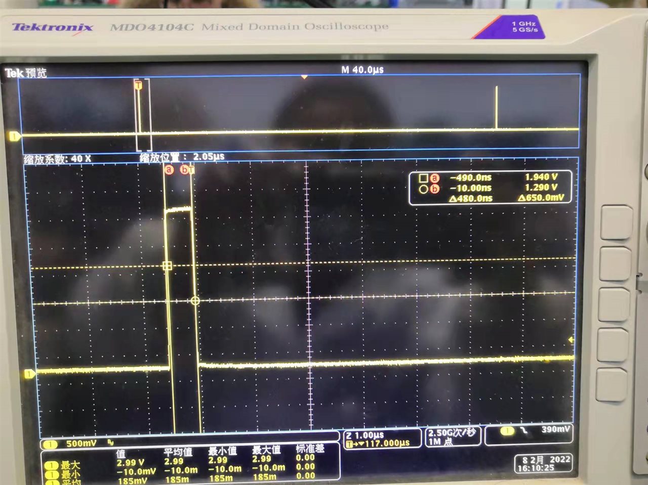
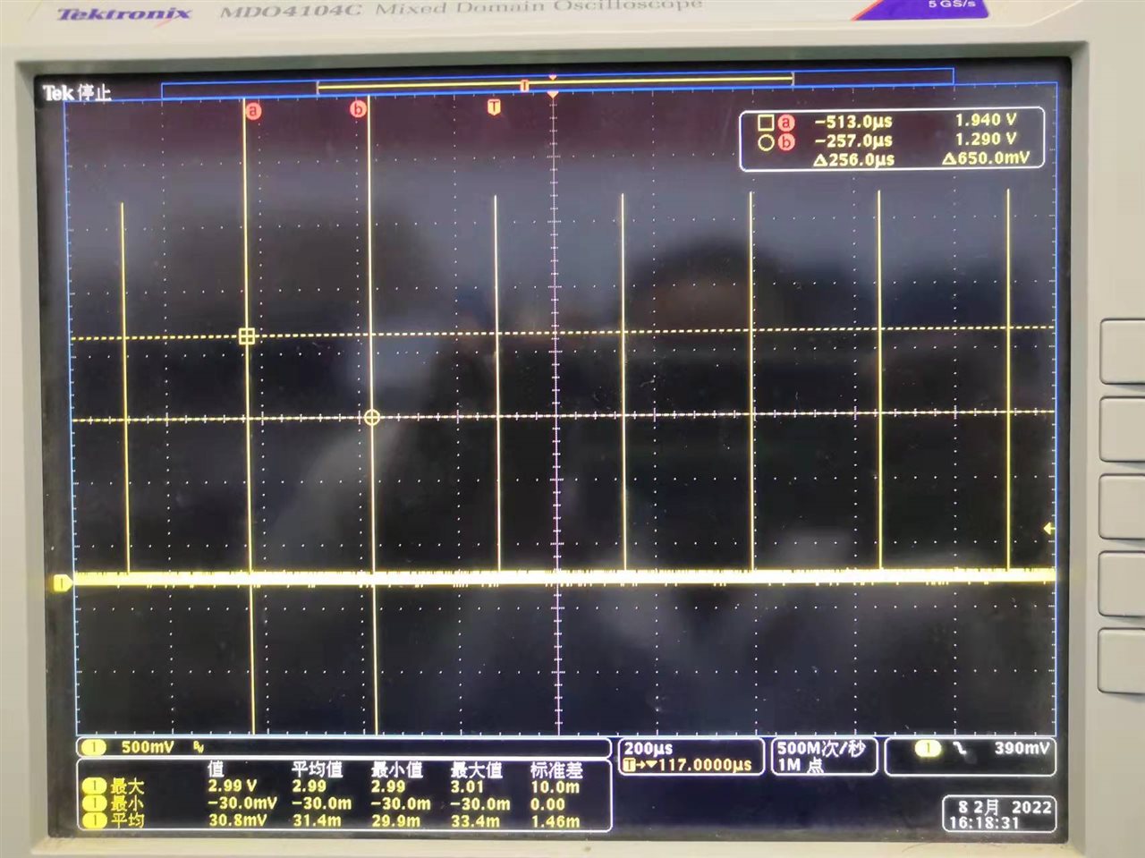
This is a new design in my customer. It is the first time for them to use ADS131M02IPW. They found DRDY output a periodic pulse with duration is about 480ns and cycle time is about 256us as below shows. What does it indicate? I would like to see if you have the same experience of that, then I will visit this customer to check more details.

Thanks.


  • Hello Jerry,

    Thank you for your post. What is the customer's question or concern? 

    DRDYn is the interrupt to indicate when new conversion data is available to read. The data rate period is measured between consecutive DRDYn falling edges. Is the device in its default register configuration during this measurement?

    Regards,

    Ryan

  • Hi Ryan,

    The DRDY pulse is too short as 400ns that the processor is hard to catch. Is there anyway to make it longer?

    This is first power-on status, so everything is default. Below is the schematics. ADS131M02 SPI interface is isolated by MAXxxx to processor, as this is an isolated ADC use case. RESET pin is actually pulled high to 3.3V. I could make it as continuous conversion mode by reset command. Correct?

    I will visit this project tomorrow, as it is a key project to breakthough sigma delta ADC for battery tester. If you have any advice to initiate to get the output data. You could share it to me.

    I got a ADS131A04EVM at customer side. How similar is register functions between M02 and A04? Customer would like to use A04EVM to evaluate the register configuration for M02, including filter and data rate setting.

    After the field support, I would move this discussion to email for more details about sigma delta ADC for battery test/BTS.

    Thanks.

  • Hi Jerry,

    Thanks for providing additional details.

    The ~400 ns DRDYn pulses are expected behavior after startup if the device is converting without reading the conversion data. There is a timing spec for the DRDYn-high pulse duration (tw(DRH)) = 4*tCLKIN (typical). Assuming the nominal CLKIN frequency of 8.192 MHz, 4*tCLKIN = 488.3 ns.

    The ADS131M02 has a two-sample FIFO memory buffer. This narrow DRDYn pulse indicates that there is still old conversion data in the buffer when a new conversion completes. To clear the FIFO and resume normal DRDYn behavior, the customer needs to either:

    1. Issue a SYNCn/RESETn pulse
    2. Read back-to-back frames before the next DRDYn pulse

    Please refer to Section 8.5.1.9.1 Collecting Data for the First Time or After a Pause in Data Collection for more information.

    I got a ADS131A04EVM at customer side. How similar is register functions between M02 and A04? Customer would like to use A04EVM to evaluate the register configuration for M02, including filter and data rate setting.

    The ADS131A04 and ADS131M02 are very different devices and I would not recommend substituting the A04 for M02 evaluation. The register map definitions as well as the analog performance are quite different. If the customer wishes to evaluate the ADS131M02, I would suggest ordering the ADS131M04EVM or contacting our product line directly if stock is limited.

    We are very excited to see the ADS131M02 being considered for battery tester applications! Please keep me in the loop by contacting me directly as you learn more about this customer opportunity.

    Best regards,

    Ryan