This thread has been locked.

If you have a related question, please click the "Ask a related question" button in the top right corner. The newly created question will be automatically linked to this question.

ADS131M08: Status flag F_RESYNC bit not setting even after a synch pulse.

Part Number: ADS131M08

I have 2 identical  ADS131M08 circuits. Individually the circuits works fine, I am able to READ/WRITE registers and able to read the data just fine. When i stack them though i have to synchronize both devices. Here is where the problem is, I am still  able to read/write register to either of the devices but im having trouble getting feedback for my software that they are synchronized. From what i know bit14 of the status register is what i have to check if a synchronization occurs. but it seems i could not get it to set

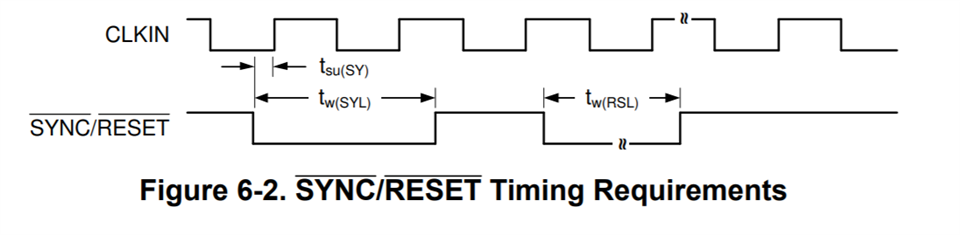
I am running on a 8.192Mhz MCLCK. I have tried several sync pulse length and still i could not get it to set ( even the recommended 1-2047 CLKIN cycles )

Here is the code i am using 

void testSYNCH(){

    uint16_t content = readSingleRegister(&device1,STATUS_ADDRESS);
    if((content & 0x4000) == 0x4000){
        printf("%s - Synchronization SUCCESSFUL.  %04X \n",device1.id,content);
    }

    else{
        printf("%s - Synchronization FAILED. %04X \n",device1.id,content);

    }

    content = readSingleRegister(&device2,STATUS_ADDRESS);
    if((content & 0x4000) == 0x4000){
        printf("%s - Synchronization SUCCESSFUL.  %04X \n",device2.id,content);
    }

    else{
        printf("%s - Synchronization FAILED. %04X  \n",device2.id,content);

    }
}


int main()
{

    init_adc_device(&device1);
    init_adc_device(&device2);

    adcStartup(&device1);
    adcStartup(&device2);

    writeSingleRegister(&device1,MODE_ADDRESS,0x0111);
    writeSingleRegister(&device2,MODE_ADDRESS,0x0111);


    gpioTrigger(5,1,0);      // 1 microsecond
    testSYNCH();
    gpioTrigger(5,5,0);      // 5 microsecond
    testSYNCH();
    gpioTrigger(5,10,0);     // 10 microsecond
    testSYNCH();
    gpioTrigger(5,20,0);     // 20 microsecond
    testSYNCH();
    gpioTrigger(5,50,0);     // 50 microsecond
    testSYNCH();
    gpioTrigger(5,100,0);    // 100 microsecond
    testSYNCH();
    gpioTrigger(5,250,0);    // 250 microsecond
    testSYNCH();
    gpioTrigger(5,500,0);    // 500 microsecond
    testSYNCH();
    gpioTrigger(5,1000,0);   // 1000 microsecond
    testSYNCH();
    gpioTrigger(5,5000,0);   // 5000 microsecond
    testSYNCH();

}


The code yields me 

Device 1 - Synchronization FAILED. 0100
Device 2 - Synchronization FAILED. 0100
Device 1 - Synchronization FAILED. 0100
Device 2 - Synchronization FAILED. 0100
Device 1 - Synchronization FAILED. 0100
Device 2 - Synchronization FAILED. 0100
Device 1 - Synchronization FAILED. 0100
Device 2 - Synchronization FAILED. 0100
Device 1 - Synchronization FAILED. 0100
Device 2 - Synchronization FAILED. 0100
Device 1 - Synchronization FAILED. 0100
Device 2 - Synchronization FAILED. 0100
Device 1 - Synchronization FAILED. 0100
Device 2 - Synchronization FAILED. 0100
Device 1 - Synchronization FAILED. 0100
Device 2 - Synchronization FAILED. 0100
Device 1 - Synchronization FAILED. 0100
Device 2 - Synchronization FAILED. 0100
Device 1 - Synchronization FAILED. 0100
Device 2 - Synchronization FAILED. 0100

I am constantly getting 0x0100 on the status registers (bit14 is 0)

Now it might be important but, I think the signals do look to get synchronized but i could not reliably reproduce this. I was getting 4200 samples for a 1 second run which led me to believe that they are synchronized else i would have gotten more.. I would like for my software to have something of an indicator that both device were truly synchronized

Before Running the program (Power was cut)

After running the program

Ay help on solving this problem would greatly be appreciated. Please let me know if you need more information on a specific portion.

  • Hello Peter,

    It looks like I can get F_RESYNC to show up in the STATUS frame when nDRDY toggles and I get the ADC data. If you just do the F_RESYNC between nDRDY toggling, you don't see the bit. Now, the documentation doesn't say this but I assume the flag gets cleared after that first STATUS word is read while grabbing data from the ADC. I'm not 100% on the criteria of when the flag is set and when it is cleared, but it sounds like you just want to make sure your ADCs are synchronized. So, I recommend you change the code to only check the synchronization on nDRDY toggles when you grab ADC data as you won't see the flag at any other time.

    Best,

    -Cole

  • Sorry but i dont quite get what you mean. By DRDY toggles you mean the time inbetween two logic LOW pulses? or you mean during DRDY is low, but that would be to fast i wont be able to complete the spi transaction (running at 5MHZ spi clock)

    So everytime DRDY pulses low the status bit synch gets cleared?

  • Hello Peter,

    Apologizes for the confusion. I originally said "between nDRDY toggling" when I should have made it clear that I'm talking about "a follow up command after a some command to read ADC". The assumptions are that:

    • The FIFO is empty. Or in other-words, ADC channel data has already been read
    • A negative falling edge on nDRDY already occurred and a command was already sent to read ADC channel 
    • The next rising edge of nDRDY shouldn't have occurred (as this would have loaded the FIFO with new ADC channel sample) 

    Does this make sense? Given all of these, you either haven't cleared out the FIFO yet, or you've already sent a command to read the ADC channel data and you're sending up a follow up command (and we don't expect to see the flag during this follow up command). From the code snippets you've posted, I'm going to guess the uncleared FIFO is the issue.

    Best,

    -Cole

  • When do i send the synch pulse? can it be just at any moment?

    I have tried to read the devices 3 times to make absolutely sure that the FIFO was empty, then synch the devices then but it still can get the bits to set though

    int main () {

       init_adc_device(&device1);
       init_adc_device(&device2);

       adcStartup(&device1);
       adcStartup(&device2);

       writeSingleRegister(&device1,MODE_ADDRESS,0x0111);
       writeSingleRegister(&device2,MODE_ADDRESS,0x0111);

      setOverSamplingRate(&device1,16384); // slowed the sampling rate to have more time between nDRDY
      setOverSamplingRate(&device2,16384);

      readData(&device1);
      readData(&device1);
      readData(&device1);
      readData(&device2);
      readData(&device2);
      readData(&device2);

      gpioTrigger(5,5,0); // 5 microsecond
      testSYNCH();

    }

    Sorry for the code formatting, inserting code is not working for me atm

  • ****but it still CAN NOT get the bits to set though

    sorry edit function is also not working for me.

  • Hello Peter,

    Please let me consult with the team on this. I had a better explanation but I'm finding some conflicting things in the datasheet about the timing. It might take until early next week.

    Best,

    -Cole

    P.S. I found your previous thread on the same subject: https://e2e.ti.com/support/data-converters-group/data-converters/f/data-converters-forum/991081/ads131m08-2-ads131m08-are-not-synchronizing 

  • Oh! I have commpletely forgotten about that... Its been a while since i last revisited this project . And it seems i have come to the same problem again, though i can get it to synchronize. But it is still very unreliable. 

    Its alright i can wait until then, Thank you for taking time helping me. I'll wait for your advice

  • Hello Peter,

    Some small helped needed from you. Can you share your schematic around the ADC and some details for the CLK and SPI interface signals?

    Initial conversations show that we might expect this issue if the CLKIN signal between the two devices are not from the same source (e.g. separate crystal oscillators connected to each device).

    Best,

    -Cole

  • The clock is not from a crystal but from a GPIO of a microprocessor. 

    (Full size image)

    Both of the devices have identical  signal sources (exempt for the SPI chip select) and are made from the schematics above. So DRDY of device 1 and 2 are connected to a single GPIO, same goes for MCLK and SYNC pins. They should theoretically be receiving the same MLCK signal

    In my old post (10 mmonths ago) i have actually probed directly on the ads131m08 to see if they were receiving the same MLCK and SYNCH pulses  (im using the exact same device as i did in my old post)

    Channel 1(Yellow) is MCLKIN as seen directly on device 1

    Channel 2(Blue) is SYNC/RESET as seen directly on device 1

    Channel 3(Pink) is SYNC/RESET as seen directly on device 2

    Channel 4(Green) is MCLKIN as seen directly on device 2

  • Hello Peter,

    Interesting development here as I got some clarification from the team.

    So the F_RESYNC register does not indicate that the device is synchronized, it indicates that a resynchronization has occurred. So if you see F_RESYNC = 0b, then either you sent a SYNC pulse and it was synchronized; or a SYNC pulse was never sent to check if the device is synchronized, or the flag has been cleared since the last time you checked. In contrast, F_RESYNC = 1b can only occur if you send the SYNC pulse and it wasn't synchronized.

    I personally don't like that fact that we don't have a bit that shows when the device is synchronized by showing a 1b in the status bit but that's the way the device works. At least, from what I can tell, you sent the SYNC pulse and got a 0b in return on F_RESYNC so you can be certain the device is synchronized.

    To answer some lingering questions, feel free to send the SYNC pulse whenever you want as the flag is updated on the CLKIN edge as determined by the datasheet spec table and datasheet description. The F_RESYNC pulse is cleared whenever the STATUS register is read explicitly, or its returned as part of a NULL command. Also, the FIFO doesn't have to be cleared for this to work, my mistake on that.

    Thanks,

    -Cole

  • Well that's a bit odd and confusing. So F_RESYNC = 1b happens when it is not synchronized? 


    What does the datasheet mean by the word "resynchronization" ? One would typically assume it is to synchronize devices especially when it says "1b = Resynchronization occurred". When its actually the opposite. 

    Is there a way to simulate a trigger a  F_RESYNC = 1b?

  • Hey Peter,

    Yes, the way I would interpret it is that synchronized or synchronization is a state, while resynchronization is an action. The intent is clearly to tell the user when the device was synchronized but something occurred (maybe a glitch or some phase shift) and the device needed to resynchronize. The problem is there is no state software flag that shows the device was or wasn't synchronized. I personally believe both are needed to help user understand what's going on. I've passed this feedback over to device definition team.

    I would simulate it by starting with SYNC following the timing criteria and alignment with CLKIN and then phase shift it so its outside of the t_su(SY), see if you can see it, and then move it back to see if it clears. 

    Best,

    -Cole

  • Thank you so much for taking the time in helping me. So in the end it is not possible to check if devices are synchronized. I do hope the datasheet gets updated to be a bit more clearer on this matter.

    Have a great day Cole ! Thank you again.

  • Hey Peter,

    No problem. The only logical conjecture I hope you consider is that: if you are absolutely certain that the MCU sent a SYNC pulse and you see F_RESYNC remained at 0b, it is logical to assume that the device is synchronized with the SYNC pulse.

    There's a lot of assumptions that must be overcome. To name a few examples: the sync pulse rising edge is the same between the two devices, and the MCU did send a SYNC pulse. However, if you can agree with those assumptions, it still be helpful in you accomplishing your goal.

    Have a great day as well.

    Best,

    -Cole