


Other Parts Discussed in Thread: OPA2171,
Hi TI Technical Support Team,
I have designed a board that includes TI 20bit DAC DAC1220 and my aim is to sweep the voltage of the load connected to my board. I am mapping 0-5V output of DAC1220 to -5V and +5V using difference amplifier as shown in the circuit. My PCB board is 4 layer, mid layers are solid GND and 5V planes and bottom and top layers are used for other analog and digital signals. DAC1220 PCB layout is made based on the recommendations and layout example given in TI DAC1220 EVM reference design file. The 3.3nF and 10nF capacitors in the schematic are film capacitor as recommended for higher precision. The 2.5V reference voltage for DAC1220 is from MCP1501-2.5V (buffered with OPA2171). There is also guard ring connected to 2.5V as recommended in DAC1220 EVM and DAC1220 datasheet. I am communicating with the DAC1220 using bit-banging, I am not using SPI. I am initializing the DAC1220 IC after 2 seconds the board is powered. These variations are also seen when I set the output to different voltages. There is always variations for the same output voltage.
My problem is there is significant variations in the output of the DAC1220. When giving power to the board, I am making initializations and setting the output to the mid value 2.5V. Every time I restart the board, I am measuring different voltages for the same 2.5V output setting (I measured as low as 2.47V and as high as 2.55V and it is changing every time). With buffer removed between MCP1501 reference voltage IC and for 2.5V output I measured as low as 2.37V for 2.5V setting. I donot know the reason.
This is not first time I use DAC1220. Actualy, I have small 2 layer board (50mmx50mm) that has only DAC1220 circuit on it. On this board, 3.3nF and 10nF capacitors are ceramic not film capacitor, MCP1501 is used as voltage reference but it is not buffered with opamp. There is guard ring connected to 2.5V. I tested this board again. I set the output to 2.5V, by powering it down and up several times I measured the output voltage and it was good enough (2.497 lowest and 2.501 highest for 2.5V desired output setting). I also tried to increment the output by 20uV every second, it also worked.
Could you please help me to find possible reason of the problem I described above?
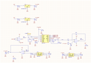
Figure 1: DAC1220 board schematic that has significant output variations. 3.3nF and 10nF capacitors are film capacitors as suggested in DAC1220 EVM and datasheet
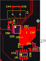
Figure 2: DAC1220 layout that has significant output variations
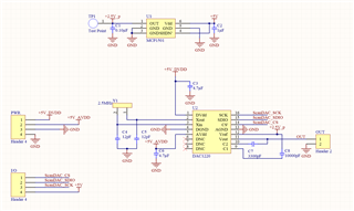
Figure 3: Previously designed working DAC1220 schematic
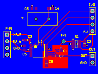
Figure 4: PCB layout for DAC1220 designed previously and working as expected.
Best regards,
Ahmet

