This thread has been locked.

If you have a related question, please click the "Ask a related question" button in the top right corner. The newly created question will be automatically linked to this question.

DAC8775: Open Wire Detection

Part Number: DAC8775

Hi team,

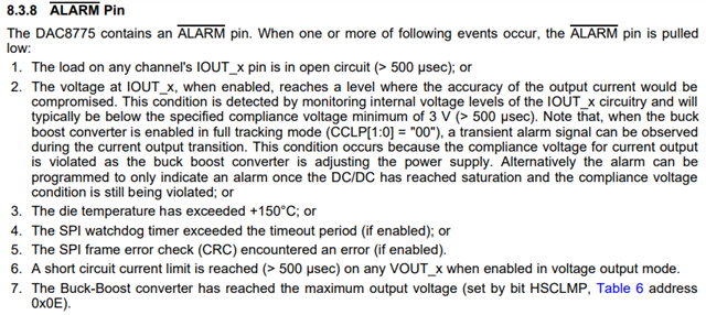
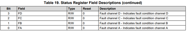
I would like to understand more on ALARM and Status Register Pin functionality in detecting open circuit condition in current mode o/p. Once the Fault is detected through ALARM pin and Open wire condition is determined by using Status Register 0x0B (bit3:0).

  1. Can we use this method to determine the open wire condition? 
  2. Here Fault Channel x (X=A,B,C,D) indicated fault on respective channel. In this context, Does channel Fault meaning either short circuit for voltage mode or open circuit for current mode?
  3. Are there any other faults other than open circuit/ short circuit channel faults?
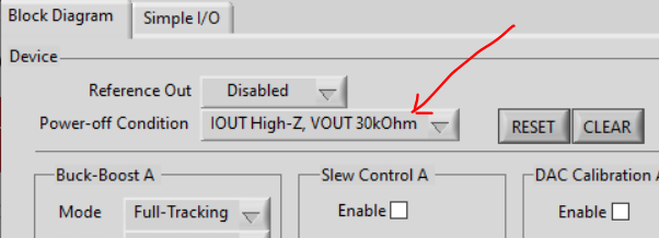
  4. I am using EVM to determine the open wire condition. I configured one of the channel in current mode. (Data loaded F). I removed the jumper on the o/p to simulate open wire condition. I have not observed any alarm when removed the jumper on the channel and Status register did not show any fault. What is the minimum current is required to determine the open wire condition in this case?
  • Hi PY,

    Joe is out of office for a few more days, so he will take a look at this when he gets back.

    Thanks,

    Paul

  • PY,

    You can use the fault indications to determine an open wire condition on IOUT (not for VOUT) however, the ALARM may indicate other faults as well.

    Once the device issues an ALARM, the device is indicating one of these 7 fault conditions from page 40 of the datasheet:

    As shown above, if the fault condition is a open-circuit current output, or the current output combined with too high of a voltage that can't be reached by the supply voltage, or if the output voltage is short circuit current limit is reached, then it will indicate the fault in the Status Field Register descriptions. There are the last four bits of 0x0B (on page 56 of the datasheet):

    With the bits above, you can see which output channel has indicated the fault.

    If the EVM to test this, you may be able to view the open wire condition for the current output. However you may need to change something in the setup. With a current output of 000Fh in the 24mA mode, this is calculates to a current of 5.5uA. The problem is that the default setting for the DAC8775 is that there is a Power-off condition that sets a VOUT 30kOhm load at the output of VOUT. Because the IOUT and VOUT are connected on this board, this is seen at IOUT during operation. With a 5.5uA at 30kOhms, the output only goes to 0.165V, so the output is technically not open. This Power-off Condition is set in the upper right corner of the EVM GUI:

    To trigger the fault you need to either remove the 30kOhm resistor so that both IOUT and VOUT are HiZ or set the DAC output to be much higher, so the output is greater than the VPOS_IN_x can be driven. Regardless, you can monitor the output of IOUT and see if the voltage goes very high.


    Joseph Wu