Because of the Thanksgiving holiday in the U.S., TI E2E™ design support forum responses may be delayed from November 25 through December 2. Thank you for your patience.

This thread has been locked.

If you have a related question, please click the "Ask a related question" button in the top right corner. The newly created question will be automatically linked to this question.

ADS1100: ADS1100 nonlinear spots in output

Part Number: ADS1100

Hello, 

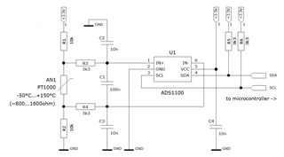
this has been touched upon earlier couple years ago. We're using ADS1100 to convert PT1000 readings. Settings are default 8 SPS and gain 8 with single conversion. We noticed freezing values which are output from ADS1100. Initially it was recorded in climatic chamber, more recently using a decade box in room temperatures. A range of 10 Ohms results in same value from ADS1100, namely 0x2AAC. This has been recorded by receiving end of i2c without doing any averaging outside ADS1100. Moreover, a similar range, ranging roughly over 5 Ohms, can be found in 0x36DD. 

If we change gain to 4, we do not see it happening with half of the output value. However, changing resistance and getting the output to 0x2AAC, it freezes again. 

Powering ADS1100 down and up doesn't affect output. Changing to continuous conversion doesn't affect output. Output is stable in general, but on "edges" of this 0x2AAC zone output is erratic inside values of +/- 0x25. 

  • I might add also here that the transition out from these spots are not fluent, rather will result in a jump from 0x2AAC to 0x2ACF in one end and 0x2A87 in the other end. As said, there's a transition area with erratic readings before jumping to the next stable value. 

  • Hello,

    Could you please provide your schematic? You mention that the nonlinearity you are seeing tends to happen at the same output codes, and not necessarily the same input. Does this happen in both of the regions 0x2AAC and 0x36DD?

    Regards,

    Scott

  • Above the provided schematics on this case. 

    You are correct. Same output code clearly is the issue, not the measured input itself. We used the resistor box instead of PT1000 in this circuit to simulate different inputs. We need to find the spot where output is either 0x2AAC or 0x36DD to get this effect. With smaller gains I'm not sure was the nonlinear spots also diminished with regards to input ranges. There might be other spots, we have been focusing on these ones only. 

  • Hello,

    What are the single-ended voltages on IN+ and IN- when the output appears nonlinear? And how does the I2C signal compare between the nonlinear region and where it seems to be operating normally? Can you capture some scope images?

    Thank you,
    Scott

  • Thank you for your response. We will do measurements at some point as soon as our setup is ready. In general the I2C output appears to operate within specs outside these specific areas.