This thread has been locked.

If you have a related question, please click the "Ask a related question" button in the top right corner. The newly created question will be automatically linked to this question.

ADS1119: 2mA drawn by single-ended analog input

Part Number: ADS1119
Other Parts Discussed in Thread: INA333,

Hi, I'm working on a project which involves the measure of whetstone bridge-based sensors (strain gauge).
Basically, there are 4 bridges, each one connected to an INA333 amplifier and to an analog input of ADS1119 ADC via RC filter.

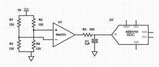
During acquisition (single-ended, gain=1, 1000 samples per second, external reference)  across R5 there is more than 1V, leading of course to incorrect measurement. If I did my math correctly, there are about 2mA going into analog inputs of the ADC. Is that current absorption normal?  (so I need to decrease R5 value)

Another problem is that I see cross-talking between channels, could be related?

Thanks

  • Hi Paride,

    You should not be seeing a large voltage drop across R5 as this would suggest current flowing through unintended places on the ADS1119 (such as the ESD diodes).  Verify that the output of the INA is within the input range of the ADC and is not exceeding the supply voltage.

    One way that this can happen is if the ADS1119 AVDD is powered by 3.3V and the INA is powered by 5V.  Also verify that the grounds are at the same potential.

    As far as the input filter values, the time constant (R*C) is quite large and will take longer to settle than the selected data rate.  So what you are seeing is analog settling when switching the input channels  I would suggest lowering the filter capacitor value.

    Best regards,

    Bob B

  • Thank you Bob,
    I will try to lower the capacitor value, even because this very low frequency cut is not required anymore.

    Both ADS1119 and INA333 are powered from the same source, and they work by 5V.
    The last time I tried, there was 2.58 V between the output of the INA and GND, but only 1.68 after R5 (and the ADC output was correct for 1.68v).

    Any ideas about the cross-talking problem?

  • Hi Paride,

    As I said previously, what you see as 'crosstalk' is analog settling.  You need to make sure that with a 16-bit ADC you need to have the analog settle fairly quickly or you will capture unsettled data between channels.

    If you are seeing a large voltage drop across R5, then either something is connected improperly or the ADS1119 is damaged.  Can you provide a complete schematic for me to review?

    Best regards,

    Bob B

  • I'll give it a try uploading as an image, I'm not sure it can be read.

    It seems to work if you click on it

  • Hi Paride,

    Thanks for the schematic.  I don't see anything that schematically would cause an unwanted current path at the inputs.  Do you see the same result for each of the inputs?  I would double check the soldering around the filter capacitors and input pins of the ADS1119.  AIN2 and AIN3 are adjacent to ground connected pins, so there could be a leakage path at those pins.

    Best regards,

    Bob B

  • Thank you, I'll do some tries in the next few days and I'll keep you updated.

    I see about 1V only on A2 and A3, I hope it is a soldering problem. I'll try to wash the board also.