This thread has been locked.

If you have a related question, please click the "Ask a related question" button in the top right corner. The newly created question will be automatically linked to this question.

ADS112C04: Trouble reading REFP/REFN (possibly a symptom of other problems)

Part Number: ADS112C04
Other Parts Discussed in Thread: LM35

Hello,

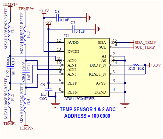
I'm trying to digitize a signal using the ADS112C04 ADC chip. I'm experiencing some trouble with using this chip so as a test, I'm trying to see if I can read REFP and REFN and AVDD and AVSS through the channels.

I'm applying a 5V voltage to the REFP and REFN pins, I've verified that the 5V difference appears on those pins with a multimeter. But when I'm programming the multiplexer such that register 0h reads 11000001 (meaning it should give me (REFP-REFN)/4), it's giving me a reading of only 48 counts. AVDD is 5V as well so I am within range. DVDD is 3.3V. 

When I set register 0h to 11010001, (AINP = AVDD, AINN= AVSS), I get ~20517 counts, which when I multiply by 2.048/(2^15-1), I get 1.28V, which is close to correct (1.25V). 

Any idea what the issue is? Why is the AVDD-AVSS setting on the multiplexer working but not the REFP-REFN one? I'm happy to provide more information.

Thanks!

Siddharth

  • Hi Siddharth,

    Welcome to the E2E forum!  Can you tell me the other register settings you are using?  Have you verified that the register settings you wrote can also read from the device?

    After configuring the MUX to measure the reference voltage, did you issue the START/SYNC command?  And did you wait long enough for the conversion to complete before reading back the conversion result?

    Best regards,

    Bob B

  • Hello Bob,

    Thanks for your response! Yes indeed, the register settings that I mentioned up here were written to the register but also verified by reading from the registers. Other registers are at their default settings (all 0). Occasionally I change the data rate but that hasn't resulted in any difference. I issued the START/SYNC command every time and I am waiting (1/sample_rate + 100 ms) just to be safe in this case. I have 6 of these chips on my board and every single one is doing this. This has been part of a larger investigation where I'm not seeing correct digitized voltage values commensurate with what is being put into the analog side.

    For completeness, I read 2 bytes, then construct my counts like so:

        reading = data[0]<<8 | data[1]


        if (reading>>15):
            reading = reading-2**16 # 2s complement to get numerical value
            voltage = reading*2.048/pgaSetting/32767
        else:
            voltage = (reading*2.048/pgaSetting)/32767

    Weirdly enough the AVDD-AVSS is showing the correct numbers.

    Thank you!


    Siddharth

  • Hi Siddharth,

    Thanks for the additional information.  A few additional questions:

    1. How are you applying the reference voltage?
    2. When you apply an external voltage to the ADC inputs, which reference do you use internal or external?
    3. Are you making sure that the source voltage (either external reference or ADC inputs) are referenced to AGND?  Fore example, REFN is connected to AGND.

    My overall concern here is that the voltage is not floating, but instead is properly referenced to ground.  I have seen many times where the source voltage + to - is correct, but with using an AC powered source can be as much as 40V from the ground of the ADC.

    Best regards,

    Bob B

  • Hello Bob,

    The arrangement we have is in the image below. We've also tried to get it to work by changing the capacitors to 10 uF.

    1) REFP is 5V, same as AVDD and DVDD - It's fed from a pretty stable 5V DC-DC regulator, which in turn is fed by a battery.

    2) The aim of this arrangement is to measure temperature from the LM35 sensor in the full range configuration with a unipolar supply (Fig. 18 here: https://www.ti.com/lit/ds/symlink/lm35.pdf, screenshot of that figure below). When I do this, I use the internal 2.048V reference. This doesn't seem to be working correctly either, which is why I first wanted to check if even REFP-REFN works.

    3) This is a little bit of an issue with the LM35 - I don't think this should affect the REFP-REFN calculation, but I should ask this question while I have your attention - Notice in the LM35 screenshot below, the negative end is a floating ground and I think this is the source of my problems with correctly measuring that differential V_out. However, it is shown in the official Lm35 datasheet so I feel like it should work.

  • Hi Siddharth,

    Any possibility that you could send me logic analyzer data of the communication?  Oscilloscope shots would even be helpful.

    Have you verified that there are no soldering issues or shorts at pin 8 and 9?  You should be able to verify that the voltage to ground is correct with a voltmeter at pin 9 as this is a corner pin.

    I have never seen or heard of an issue monitoring the reference.  If you see the same issue on multiple devices this might indicate that there might be an issue common to all of the devices.  Check the layout and make sure that the schematic and layout match precisely.  For example, check and make sure that the REFN is actually connected to ground and REFP is actually connected to the 5V source.

    As to the LM35, I really don't have any experience with this device.  The circuit as presented should work as long as the grounds are common (the ADC AGND, the ground at the 1N914 and the ground at the 18k resistor).  The one thing I did notice is the LM35 does not handle driving cap loads.  So the 1nF load may be too large.

    Best regards,

    Bob B

  • Hi Bob,

    I'll try to look into getting the oscilloscope shots. I have verified that there are no soldering issues. We directly measured the voltages off the pins and they showed 5V but for some reason it's not showing up in the counts. Your comment about the LM35's capacitance was a lifesaver - it never struck us that 1nF would be too high. We replaced that with a 75 pF capacitor and it worked perfectly! So now we have a weird situation where the differential inputs are working correctly but the external reference ones are not. I'm also beginning to wonder as a result if there's something I'm doing wrong in software.

    Siddharth

  • Here's another thought - when measuring VREFP-VREFN, aside from setting register 0 as 11000001, do I also need to set bits 2:1 in register 1 as 01 to use the external reference? I had register 1 in default all 0s setting.

  • Hi Siddharth,

    Yes, you need to select the external reference.  There is a very small mention in the section 8.3.1 where it states:

    "For system-monitoring purposes, the analog supply [(AVDD – AVSS) / 4] or the currently selected external reference voltage [(VREFP – VREFN) / 4] can be selected as inputs to the ADC."

    So yes, you should select the external reference in register 1.  When you set the mux input to (VREFP – VREFN) / 4, the measurement will automatically use  the internal reference  with a gain of 1 to measure the reference voltage.

    Best regards.

    Bob B

  • It worked! It is a bit strange that the internal reference works for AVDD-AVSS but doesn't for REFP-REFN. As a suggestion - it might be useful to mark that in the tables that define the registers so it's very clear :)

    Thanks a lot for your help, you solved two of my problems for the price of one!