This thread has been locked.

If you have a related question, please click the "Ask a related question" button in the top right corner. The newly created question will be automatically linked to this question.

ADS114S08B: No Signal from MISO

Part Number: ADS114S08B

Hi!

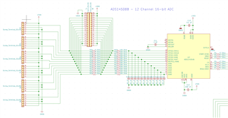
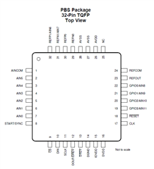
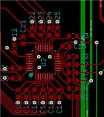
I am implementing the ADS114S08B into a custom design and am having trouble communicating with it. I have used the recommended layout with 47 Ohm resistors in series on the SPI traces and have confirmed that the pinout is correct. I am operating the IC at 3.3V with an analog supply at 5V (supplied by independent LDO). The SPI bus is also connected to a slave microcontroller and is operating normally.

I am using an Atmel SAM microcontroller with SPI configured at 1Mhz, MSB first, and Mode 1 as per the datasheet.

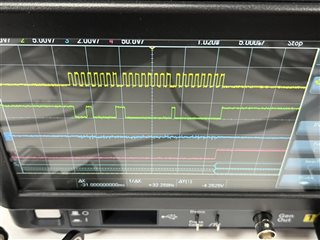
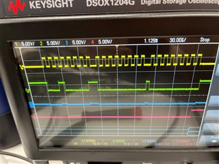
The pictures I am including showing an attempted RREG command for the status register. The MOSI byte sequence is 0x21 0x0 0x0.

From top to bottom -> SCLK, MOSI, MISO, CS.

The issue that has been persisting is that I am unable to get a response from the MISO (DOUT) port on the ADC. There is some noise generated at each edge of SCLK but otherwise no response. Do you have any recommendations?

Thank you!

  • Hi Charles,

    Welcome to the E2E forum! It would be helpful to see your schematic.  There are a few common mistakes.  Make sure that all of the supplies are at nominal operating voltage (IOVDD/DVDD/AVDD) otherwise the ADC is held in a reset state.  Make sure that the analog ground and digital ground are connected together.  Also make sure that the RESET pin is pulled high and that the CLK pin is pulled low.

    Best regards,

    Bob B

  • Thanks Bob!

    I have attached my schematic below. The SPI bus and control pins are tied directly to the microcontroller.

    I probed the supplies and confirmed continuity between AVSS, DGND and my ground plane. IOVDD and DVDD are both operating at 3.3V and AVDD is operating at 5V. I can also confirm that the RESET pin is pulled high via external GPIO. I directly tied my CLK pin to ground in the schematic and it is showing continuity with the ground plane.

  • After slowing the SPI frequency to 100kHz I have this on my oscilloscope. I hope it helps figure out whats going on... It seems like a reset problem as you said before.

    Top to bottom: SCK, MOSI, MISO, CS

  • Hi Charles,

    I would verify that the signals are getting beyond the 47 Ohm resistors and that there is no soldering or board issue and the device is actually seeing the signals.  In particular the RESET, SCLK, CS and MOSI.  Also verify that the supplies are valid at the device pins.

    How are you controlling CS?  Make sure that you are holding CS low long enough following the last edge of SCLK as specified in the SPI timing diagram in the datasheet.  This appears to be violated in the last scope shot.  This should not prevent the data from coming out, but it could be an issue when writing.

    Best regards,

    Bob B

  • Hi Bob,

    I confirmed supplies directly at the device pins. I also probed the CS, MOSI and MISO lines on both sides of the resistors as well as on the pins and saw no difference in the scope output. RESET is confirmed always pulled high.

    I set CS to be low with a millisecond buffer before the first clock cycle and after the last clock cycle and there is no change in behavior.

    As the MISO channel was showing some noise mimicking the MOSI channel I checked the resistance between the two and found it to be ~3 MOhms which should be fine?

    I'm a bit unsure how to proceed. I have 4 boards total and all are showing the same issue.

    Thanks!

    Best Regards,

    Charles

  • Hi Charles,

    Which device package are you using?  One other thing you can check is to make sure that the device footprint for the PCB is precisely matching the device pinout.  I have seen occasions where the footprint is actually reversed in direction.  If you have gerber files I would be glad to review them for you.

    The next step I would suggest is to power up the ADS114S08B and pull the START/SYNC pin high.  If the device is operational, then the ADC should start converting and pulse DRDY at the default data output rate of approximately 50ms.  If you see this pulse, then we will know where to proceed next.  If we don't see this pulse showing that the ADC is converting, then we can dig deeper into reset or power issues.

    Best regards,

    Bob B

  • Hi Bob,

    I am using the 32-Pin TQFP package. I believe that the orientation is correct but I will double check.

    I am not seeing any pulse on the DRDY line. I am however able to observe 3.3V on it. I am attaching a screenshot of my device footprint as well as of the PCB layout. The board is 1.6mm thick with 4-layers, the red is top plane and green is bottom plane.

    Thank you!

  • Hi Charles,

    As far as I can tell you have things connected properly, but as I cannot see the inner layers it is difficult to know for sure.  If there is no action with the device having the START/SYNC pin high, then there can only be a few possibilities as I outlined at the start.  So there can only be a code issue, an issue with the SPI connections, a supply issue, or the RESET pin is floating or low. 

    Have you verified with an Ohm meter that the AGND and DGND are connected together?  Have you verified all the connections and voltages at the ADC supply pins?  Have you verified that MISO and MOSI are correctly connected (and not reversely connected)?  Undoubtedly you have checked and rechecked, but the thing is that if you have 4 boards showing the same behavior, then there is something that is being missed in your troubleshooting.  I would go back to the very beginning and check and probe each point as close as possible to the ADC device pins. 

    If the DRDY pin is not toggling with the START/SYNC pin high, you can concentrate on the RESET pin and supply pins first until you get the ADC working in the default configuration.  Once you have that working, then you can verify your SPI communication.

    Best regards,

    Bob B

  • Hi Bob,

    Thank you so much for your help. It ended up being a analog power supply issue. I had disconnected the 5V power supply from the analog side of the board to isolate it from other subsystems. I assume my original problem was in software configuration which was then compounded by the disconnected power supply. Everything is working correctly now!

    Thank you!

    Best Regards,

    Charles