This thread has been locked.

If you have a related question, please click the "Ask a related question" button in the top right corner. The newly created question will be automatically linked to this question.

ADC3662EVM: ADC3662 Signal Max. Input Voltage

Part Number: ADC3662EVM
Other Parts Discussed in Thread: ADC3662,

Dear Ladies and Gentlemen,
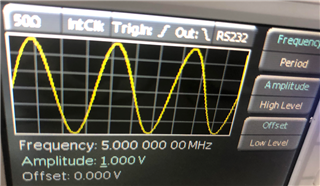
We have recently acquired an ADC3662EVM and a TSW1400EVM. We have tried to put the device into operation with the help of the userguide. We use the internal clock instead of an external clock. The hardware modifications were made as described. Now we wanted to connect an external signal to the adc as described, but we are not quite sure how many volts the input signal may have maximum. Since the user guide only describes that the signal should have ( 5 MHz at a power level of ~ +15 dBm), but we have to set the amplitude power level and offset on our signal generator, we looked for the internal resistance of the analogue input in the data sheet of the ADC to calculate the max voltage. But we were not quite sure what the internal resistancee of the ADC3662 is and how high the maximum voltage of the signal may be.

Many thanks in advance.

Kind regards

Quirin

  • Quirin,

    The analog input voltage is shown in the datasheet below as 3.2Vpp. Your signal generator does not require a DC offset. Any DC component of your input signal will be removed by the analog input balun because baluns are inherently AC coupled. If you wish to preserve the DC component of your input, you will need to modify the EVM for DC coupling operation.

    I suggest to begin with a low power level (example 5dBm) on your signal generator and slowly increase the power level until HSDC Pro reports the tone as approaching fullscale (example -0.5dBFs). Fullscale is at 0dBFs. You want to operate the part below fullscale. (Shown below is for a different ADC so numbers will be different, however this is meants to show where the Fundamental measurement is relative to fullscale of the ADC. Shown in this image is -12dBFS meaning this particular ADC can accept an input tone that is 12dBm higher that what is currently being applied to the input.)

    Thanks, Chase

    Edit: I'm not sure why the images are blurry. If you click on the image(s), it will appear much more clear.

  • Dear Chase,

    I tried it like descriebed but unfortunatly I dont get an logic output.

    Thanks Quirin

  • Hi Quirin,

    Your EVM is setup for 10MHz onboard clocking, yet HSDC Pro shows the sample rate as 25M, this will still capture (as you can see some noise floor), however the fundamental is not going to appear at the correct frequency of 5MHz. Instead, since the data is coming in 2.5x slower than HSDC Pro is expecting, the tone will appear at 2.5x higher than the actual input tone. So, if you look closely, you can see the fundamental at 12.5MHz. To correct this, change the ADC output data rate to 10M or switch the ADC configuration for 25MSPS.

    Thanks