This thread has been locked.

If you have a related question, please click the "Ask a related question" button in the top right corner. The newly created question will be automatically linked to this question.

DAC3482EVM: Control TWO DAC3482EVM on the same PC using GUI or DLL

Part Number: DAC3482EVM
Other Parts Discussed in Thread: CDCE62005, DAC3484, DAC3482

I want to control two 3482EVMs in my system and I have few questions:

1. Is it possible to set each card registers with the EVM GUI? I don't see anywhere on the UI an option to choose port or device.. 

2. For controlling programmatically I am using the DLL. When connecting to the two devices I saw that I should use different index in the OpenUSB function. How do I know which index belong to which card?

is it permanent and set when connecting to the PC for the first time? or it can change upon power cycle etc.?

3. I want also to control the CDCE62005 with the DLL - but I didn't understand how to connect it. Should I just initialize it with the appropriate pattern file and using a different device-index from the DAC?

Thanks

Itay

  • Hi Italy,

    The current GUI and the SPI utilities are designed with 1x DAC3482 EVM control. It is possible to modify the DAC3484 FTDI instantiation and also the SPI utilities on your own to control multiple DAC3482 EVMs

    1. refer to the following forum for references on DAC3482 SPI control utilities

    https://e2e.ti.com/support/data-converters-group/data-converters/f/data-converters-forum/432855/dll-of-dac348x-evm-software-gui?tisearch=e2e-sitesearch&keymatch=dac3484%252520dll#

    2. download FT PROG from FTDI website and instantiate the name of the FTDI chip so the two EVMs have different naming. 

    3. modify the SPI software accordingly (your own development) to accommodate both EVMs

  • Thanks 

    I am able to connect to both cards using the DLL and different indexes and the same name (however - I don't know which is which). 

    Is it safe to change the card name? there is a warning in FT_PROG that writing to the EEPROM can make the chip useless...

    I have another problem - I'm using the DAC3482 pattern file from the zip in the link you sent. 

    Reading registers works as expected. However - writing doesn't. When I try to write for example to REG x03 a certain value (e.g. 0x2001) - I read a different value from the register after each writing and it is completely different from 0x2001. 

    Could it be that there is something wrong with the pattern file? could it be that I should use different file if for example I'm using 3pin and not 4pin for communication?

    P.S. in the link there is another pattern file for DAC348x - different from the one in the zip file. When trying to use it I get always zeros upon reading registers. 

  • Hi Italy,

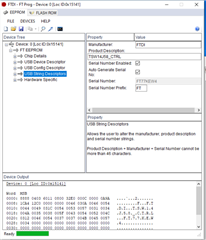
    You will have to check with the FTDI support to be sure. We have usually change the USB String descriptor without any issue. See below. However, since the device owner is FTDI, please check with them.

    Reading registers works as expected. However - writing doesn't. When I try to write for example to REG x03 a certain value (e.g. 0x2001) - I read a different value from the register after each writing and it is completely different from 0x2001. 

    We so far have not yet heard any problems on the write and read as the GUI had been released for a while. The read and write cycle share the same instructions up to the address cycle. Will you be able to probe the SCLK, SDI, SDO, and SDEN to ensure the setup/hold time are proper and the right datastreams are what you wrote. 

  • So the same pattern is appropriate for 3-pin or 4-pin SPI communication?

    I will try probe the signals and update 

  • Hi,

    The DAC3484 default configuration for the GUI is set to 3 pin. 

    Since you are reading back OK, the SDIO setting must be correct. The difference in 4 pin between read and write is the SDO output. 

  • ok, thanks.

    I tried both 32 and 64 dll and write_register fails like I described on both..

    Could it be some other SIF settings? maybe a different baud_rate?

    I don't understand how does it work with the EVM main GUI but not with the dll?

  • Hi Italy,

    Please advise if you have the scope capture for the write process: i.e. SCLK, SDIO, SENB all in one plot and the register you are trying to write.

  • Yes, just did it now.

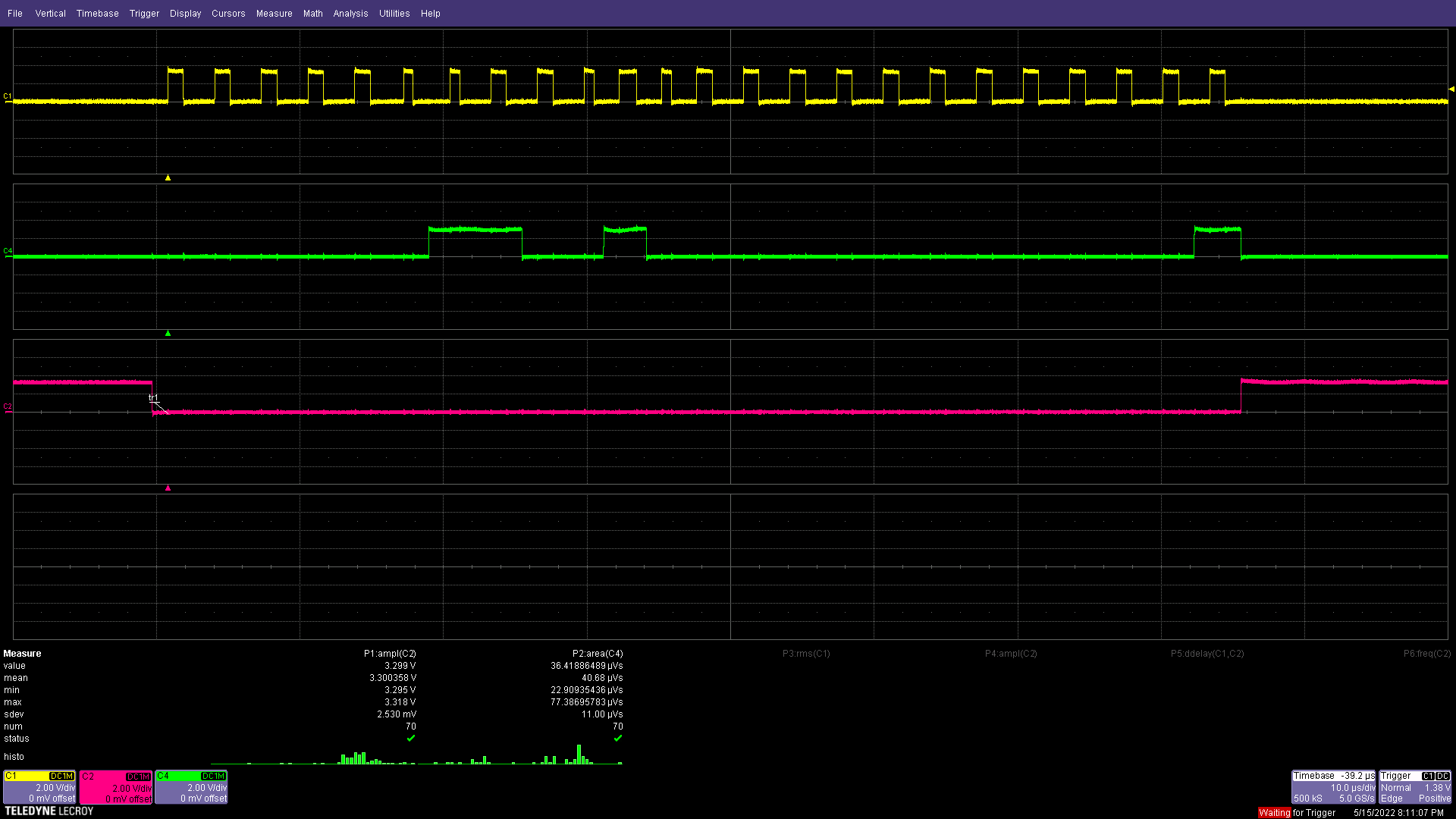
    Here is the output on scope while writing 0x2001 to register 0x03 using main GUI (which works):

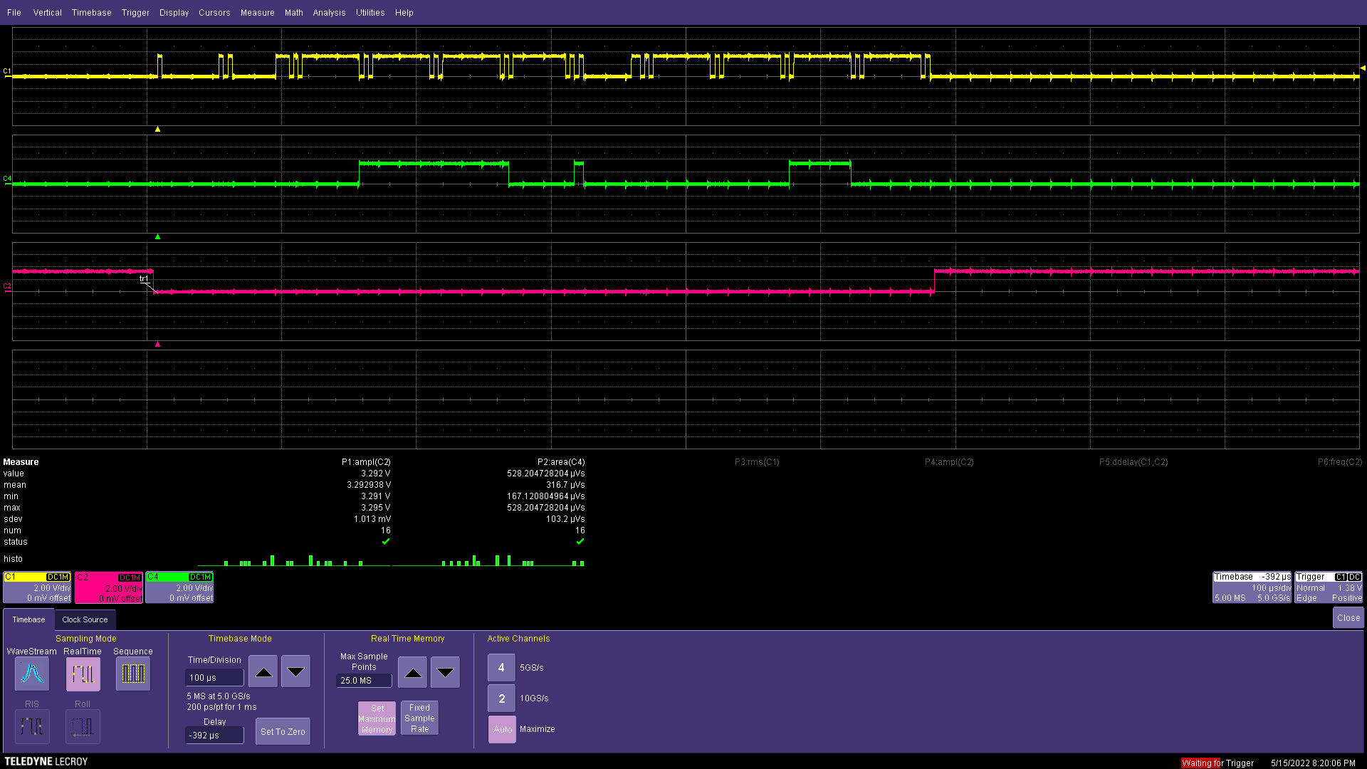
    And here are the signals when using the DLL (which fails to write the correct data):

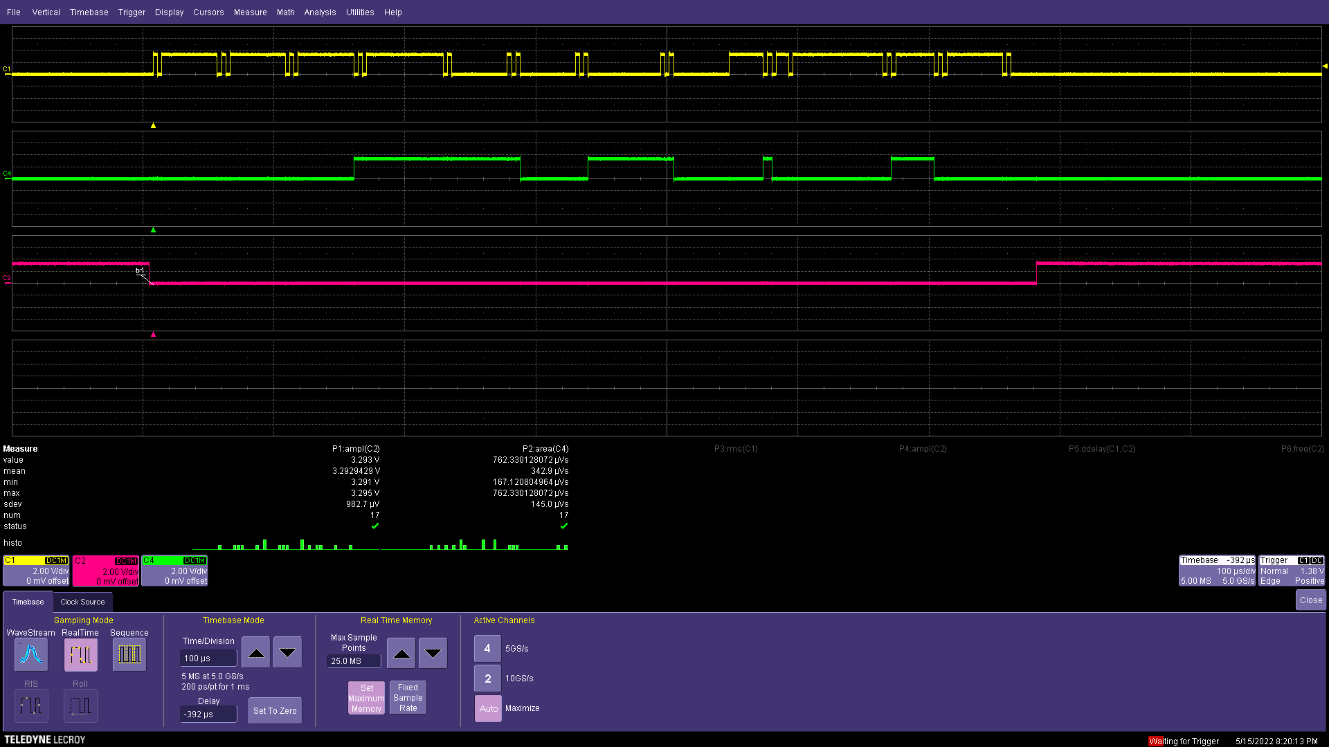
    Here is another attempt which give a different signals output (using similar values in the DLL):

    Seems like the entire communication behaves wrong.

    The read scenario also looks bad like the write but it does work - I read the correct values when comparing to the main GUI.

    Please advise.

    Thanks

  • BTW, I used 19200 baud-rate in the above run (I later tried higher rates but writing the correct value still failed).

    In addition - I tried both 'writeRegister_64' and 'writeRegister' DLL functions and both gives same results.

  • Hi Italy,

    I am not sure what went wrong. Let me check with the team who developed this to see if they have any feedback.

    -Kang

  • Hi Italy,

    We could not duplicate your issue

    See below:

    The DLL should work without any issues. We tried to write to a register with the DAC3484 board using a LabVIEW VI, which uses the FTDI Pattern generator DLL, and we don’t see any issues in writing and reading it back.


    Could you please double check if you are using the FTDI Pattern Generator LabVIEW Example.vi that was shared earlier or using the DLL in any other platform?

     https://tidrive.ext.ti.com/u/g6HJmQMhyc6Rocmd/d02848a4-c940-4967-a640-6e2a93b2cf83?l

    In the case of LabVIEW, could you use the FTDI Pattern Generator LabVIEW Example.vi to write to a register and read back? We can try this with only one board connected to the PC and close the Device GUI and see if the issue happens.


    The Device description of the FTDI port and Baud rate can be found in the FTDI cfg.ini present at the DAC3484 GUI installed location.


    Default Installation Location : C:\Program Files\Texas Instruments\DAC348x


    If there are no issues in writing to a register with Example VI, then the DLL might not have the issue.

  • Did you try it with 3482 EVM on 64-bit system with the 64bit DLL?

    I don't have Labview installed in the machine.. 

    I'm using the DLL with python.

    Also, I don't see anything regarding baud-rate in the ini file. here is its content:

    [DAC3484_GUI_v3p8]
    server.app.propertiesEnabled=True
    server.tcp.serviceName="My Computer/VI Server"
    server.vi.propertiesEnabled=True
    WebServer.TcpAccess="c+*"
    WebServer.ViAccess="+*"
    DebugServerEnabled=False
    DebugServerWaitOnLaunch=False

  • please let me discuss with the team and get back to you. We can perhaps give you a compiled version for you to test.

  • Hi Italy,

    is it possible to share your python script for us to look into this? Please also share the python version. Thank you.

  • Sure:

    Python version 3.8.

    Script:

    from ctypes import *
    import os
    
    
    orig_cwd = os.getcwd()
    os.chdir(r'D:\dev\DAC348xEVM_SPI_Utilities\64-bit DLL\FTDI Pattern Generator')
    dll_file_name = r'FTDI_Pattern_Generator.dll'
    dll_path = os.path.join(os.getcwd(), dll_file_name)
    dll = CDLL(dll_path)
    
    evm_index = c_int(0)
    device_index = c_int(0)
    
    dev_desc = 'DAC348xEVM'
    # baud_rate = 19200
    baud_rate = 230400
    pattern_file_name = 'DAC348x.txt'
    pattern_file_path = os.path.join(os.getcwd(), pattern_file_name)
    
    write_address = c_ulong(0x03)
    write_data = c_ulong(0x2001)
    
    write_address_64 = c_ulonglong(0x03)
    write_data_64 = c_ulonglong(0x2001)
    
    read_address = c_ulong(0x03)
    read_data = c_ulong(0)
    
    read_address_64 = c_ulonglong(0x03)
    read_data_64 = c_ulonglong(0)
    
    error_status = dll.openUSBPort(dev_desc.encode(), baud_rate, byref(evm_index))
    print(error_status)
    print(evm_index.value)
    
    error_status = dll.initializeDevice(pattern_file_path.encode(), evm_index, byref(device_index))
    print(error_status)
    print(device_index.value)
    
    # error_status = dll.readRegister(evm_index, device_index, read_address, byref(read_data))
    # print(error_status)
    # print(hex(read_data.value))
    
    error_status = dll.readRegister_64(evm_index, device_index, read_address_64, byref(read_data_64))
    print(error_status)
    print(hex(read_data_64.value))
    
    # error_status = dll.writeRegister(evm_index, device_index, write_address, byref(write_data))
    # print(error_status)
    
    error_status = dll.writeRegister_64(evm_index, device_index, write_address_64, byref(write_data_64))
    print(error_status)
    
    error_status = dll.closeAllPorts()
    print(error_status)

  • Sorry - I found the error in my code..

    I sent the ref to write_data instead of the data itself..

    Thanks for the support