This thread has been locked.

If you have a related question, please click the "Ask a related question" button in the top right corner. The newly created question will be automatically linked to this question.

ADS41B29: ADS41B29

Part Number: ADS41B29
Other Parts Discussed in Thread: ADS5407

Hi

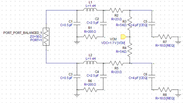
I am rather curious to know why when I simulate the internal input circuit for AS41B29 as shown on page 26 of the datasheet, I DO NOT get the plots shown on page 48.  Either you have not defined something or I have messed up the simulation but I am fairly experienced with this (or so I think). Here is the circuit below in Keysight Genesys

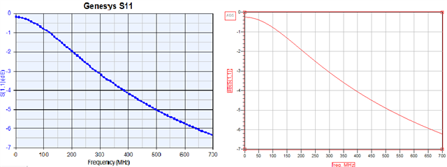
Here is a comparison in s11 between Genesys and ADS, so the simulator is not the issue

And here is a comparison of Rin between what you proport in the paper and what the actual simulation produces (i.e. I am simply taking the real part of Zin here).  The bright blue is the paper, the dark blue is what I simulate:

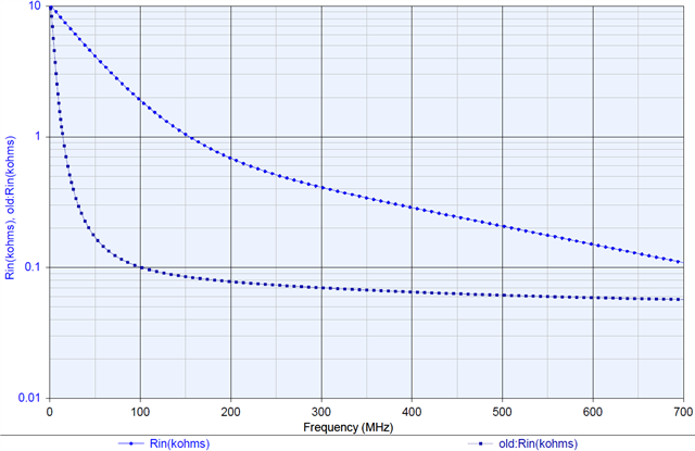
I would really like a circuit to simulate the complex input Rin and Cin.  Can you please tell me what I have done wrong and/or how you have simulated this because that circuit does not represent what you show?

Cheers,

Nima

  • Hi Nima,

    the circuit above is a simplified model of the parasitic, not the exact transistor model of the actual design. TI cannot release to you the actual design file for simulation as it is our IP.

    -Kang

  • Hi Kang

    I am not after TI IP but I do think when you show an equivalent circuit with so many components, it should actually match what you expect to see.  The difference between these is huge, so much so in fact that I would be better off not simulating it at all and assuming some flat number.  I think this is a bit of a problem and I am also seeing this with other ADCs you produce such as ADS5407.  

    I have managed to build a Z11 model based on the plots on page 49 of the schematic which is what I should have done first.  This information does not exist for other ADCs, or does it? For example, do you have such plots of Rin and Cin for ADS5407?

    Cheers,

    Nima

  • Hi Nima,

    My understanding from discussing with designer is that the ADC front end is very dynamic as there are transistors switching on/off. Nevertheless, we are checking internally and will get back to you. As these are fairly legacy product, it will take time to find answers. Please understand. 

  • Hi Nima,

    According to silicon designer, it is not possible to converge a transient model into a static model completely.  This is a known limitation both in the academic and industry. The models will be approximate as ADCs are inherently a sampling device with Nyquist property. It is not a traditional op-amp circuit where all the transistors are biased without switching (i.e. clocks)

    You may see the following models as example:

    https://www.ti.com/product/ADS62P49#design-tools-simulation